Nailor Industries Inc. reserves the right to change any information concerning product or pricing without notice.
SCHEDULE TYPE:
PROJECT:
ENGINEER:
CONTRACTOR:
DATE B SERIES SUPERSEDES DRAWING NO.
2 - 6 - 23 3500 11 - 15 - 22 35SST-1
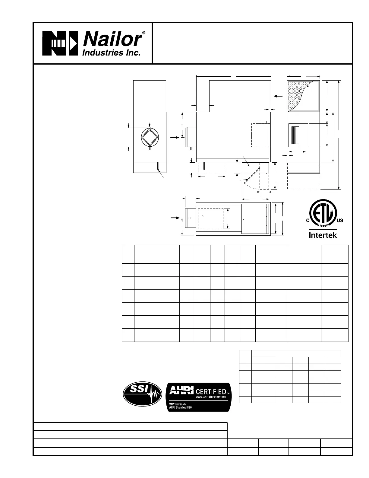
FAN POWERED TERMINAL UNIT WITH
EPIC ECM MOTOR
STEALTH • SERIES FLOW
CONSTANT OR VARIABLE VOLUME
MODELS: 35SST, 35SWST AND 35SEST • UNIT SIZES 1 – 6
L
W
2
MULTI-POINT
FLOW SENSOR
FAN
7 1/4"
(184)
1" (25)
B
DW
DH
IW
W
OPTIONAL
INDUCED
AIR FILTER
1" (25)
DRIVESHAFT
PRIMARY
AIR
INDUCED
AIR
IH
DIA. =
NOM. –
1/8" (3)
5 3/4"
(146)
14" (356)
14" (356)
H -
1" (25)
H
HINGED FAN
CONTROLS
ENCLOSURE
OPTIONAL
PRIMARY
AIR VALVE
CONTROLS
ENCLOSURE
11"
(279)
HINGED
FAN CONTROLS
ENCLOSURE
PRIMARY
AIR
5 1/2"
(140)
H
2
6 3/4"
(171)
W2
5 3/4"
(146)
15"
(381)
OPTIONAL
90° FN2
CONTROLS
ENCLOSURE
Dimensional Data
Model 35SST • Basic Unit
**
ECM Only.
Unit
Size
Inlet
Size
W W2 H L B
Induced Air
Inlet
IW x IH
Outlet
Discharge
DW x DH
Filter
Size
1
5, 6, 8**
(127, 152, 203)
20
(508)
44
(1118)
14
(356)
36
(914)
6
(152)
9 x 14
(229 x 356)
8 1/8 x 4 1/4
(206 x 108)
10 x 14
(254 x 356)
2
6, 8
(152, 203)
18
(457)
42
(1067)
14
(356)
36
(914)
3 1/2
(89)
9 x 14
(229 x 356)
9 1/4 x 10 1/2
(235 x 267)
10 x 14
(254 x 356)
3
6, 8, 10, 12
(152, 203, 254, 305)
18
(457)
44
(1118)
18
(457)
36
(914)
3 1/2
(89)
11 x 18
(279 x 457)
9 1/4 x 10 1/2
(235 x 267)
12 x 18
(305 x 457)
4
8, 10, 12, 14
(203, 254, 305, 356)
26
(660)
56 3/4
(1441)
18
(457)
41
(1041)
6
(152)
15 3/4 x 14
(400 x 356)
12 x 10 1/2
(305 x 267)
16 x 14
(406 x 356)
5
10, 12, 14
(254, 305, 356)
26
(660)
55 1/2
(1410)
18
(457)
41
(1041)
5
(127)
14 1/2 x 18
(368 x 457)
13 1/4 x 11 1/2
(337 x 292)
14 x 18
(356 x 457)
6
12, 14, 16
(305, 356, 406)
30
(762)
62 1/2
(1588)
19
(483)
44
(1118)
6
(152)
17 1/2 x 19
(445 x 483)
13 1/4 x 11 1/2
(337 x 292)
18 x 19
(457 x 483)
DESCRIPTION:
• 18 ga. (1.31) galvanized steel
channel frame with 20 ga. (1.00)
casing components.
• 16 ga. (1.61) galvanized steel
inclined opposed blade
damper. 45°
rotation. CW to close.
• Ultra-high efficiency ECM fan
motor. EPIC fan volume controller.
• Multi-point averaging Diamond
Flow sensor. Supplied with balancing
tees.
• Full size access panels on three
sides.
• 3/4" (19) dual density insulation,
exposed edges coated to prevent
air erosion. Meets requirements of
NFPA 90A and UL 181.
• Single point electrical and /or
pneumatic main air connection.
• Discharge opening for flanged duct
connection.
• Full primary air valve low voltage
NEMA 1 type enclosure for factory
mounted DDC and analog electronic
controls.
• Controls mounted as standard
on RH side as shown. Terminals
ordered with LH controls (optional)
are inverted and discharge duct
hanging elevation will therefore
change.
OPTIONS:
Digital Controls:
q Factory mounted (supplied by
others)
q Field mounted (supplied by others)
q
Nailor EZvav. See separate submittal.
Liner:
q Steri-liner
q Steri-liner + Perforated metal
q Fiber-free
q Perforated metal
q Solid metal
q 1" (25) fiberglass
q Low temperature construction
Other:
q Left-hand controls location
q Toggle disconnect switch
q Fan unit fusing
q 24/24V Isolation transformer
q Cross Flow Sensor
q 'Q' Option – Induced Air Inlet
Attenuator
q Top entry induced air inlet
q 1" (25) Throwaway filter
q 2" (51) MERV 8 filter
q Hanger brackets.
q 1/4-turn fasteners (access panel)
q FN2 90° Line Voltage Enclosure
q FN3 Remote Line Voltage
Controls Enclosure
(See submittal FN3)
q Dust tight enclosure seal
q Remote user disconnect
Seismic Certification:
q Seismic Source International (Standard)
q HCAI (formerly OSHPD, California)
q Special Features: _________ .
Listed
Page 1 of 2. For heat options; see page 2.
Dimensions are in inches (mm).
Unit
Size
EPIC ECM Motor FLA
Motor HP 120V 208V 240V 277V
1
*
2.1 1.4 1.3 1.2
2
*
4.0 2.7 2.6 2.6
3
*
5.0 3.4 3.3 3.3
4
*
6.9 4.6 4.5 4.2
5
*
9.0 6.1 5.8 5.6
6
*
11.9 7.3 7.3 7.2
*
The ECM is a variable horsepower motor. Refer to
Selectworks schedule for actual power consumption.
FLA = Full load amperage. All motors are single
phase/60 Hz.
Electrical Data
 Loading...