EasyManuals Logo

NAiS FP1 User Manual

Default Icon
280 pages
To Next Page IconTo Next Page
To Previous Page IconTo Previous Page
Page #118 background imageLoading...
Page #118 background image
5-3. Description of Basic Instructions
110
Notes:
Application examples
R1
R0
X0
X0 R3
( DF/ )!
R0
X0 R0
( DF )!
R3
R2
R3
R0 Y0
R1
X0 R1
( DF/ )!
R3
R0
R2
X0 R2
( DF )!
R3
R1
R2
R2
Y0
R0
X1
X0
Y0
X1 R0
( DF )!
X0 Y0
( DF )!
R0
Y0
Y0
A program with a DF instruction
R0
X1
X0
Y0
X1 R0
X0 Y0
R0
A program without a DF instruction
Alternating circuit using a single signal to hold and
release a circuit.
Self-hold circuits when the output is controlled by
a long input signal.
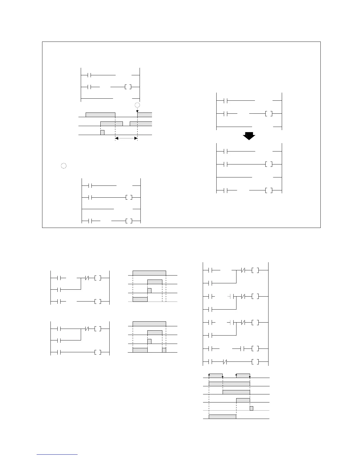
Trigger to the DF instructions between the MC
and MCE instruction set are ignored while the
MC execution condition is OFF.
If, in the example above, output is required at
point A , place the DF instruction outside the MC
and MCE instruction set.
If the same trigger is set for the MC and for the
DF instruction, there will be no output. Place the
DF instruction outside the MC and MCE
instruction set when output is required.
INCORRECT
( MCE 0 )!
X0 Y0
( DF )!
X0
( MC 0 )!
( MCE 0 )!
X0 R0
X0
( MC 0 )!
R0 Y0
( DF )!
Y0 never
turns ON.
( MCE 0 )!
Y0
X1
X0
X1 Y0
( DF )!
X0
( MC 0 )!
Changes in X1 are ignored
during this interval.
A
( MCE 0 )!
X1 R0
X0
( MC 0 )!
R0 Y0
( DF )!

Table of Contents

Questions and Answers:

Question and Answer IconNeed help?

Do you have a question about the NAiS FP1 and is the answer not in the manual?

NAiS FP1 Specifications

General IconGeneral
BrandNAiS
ModelFP1
CategoryController
LanguageEnglish

Related product manuals