41
3. Cautions
• Install and remove the Control Unit, Expansion Unit, FP1 A/D Converter Unit, FP1 D/A Converter Unit, and FP1 I/O
Link Unit when all power is turned OFF.
• Do not drop the unit or apply excessive force to it.
• Do not allow pieces of wire or other objects to fall into the unit when wiring.
• Do not use the unit where it will be exposed to the following:
- Ambient temperatures of 0˚C to 55˚C (32˚F to 131˚F).
- Ambient humidity of 35 % to 85 % RH.
- Sudden temperature changes causing condensation.
- Inflammable or corrosive gas.
- Excessive airborne dust or metal particles.
- Benzine, paint thinner, alcohol or other organic solvents or strong alkaline solutions such as ammonia or caustic
soda.
- Excessive vibration or shock.
- Influence from power transmission lines, high voltage equipment, power cables, power equipment, radio
transmitters, or any other equipment that would generate high switching surges.
- Water in any form including spray or mist.
- Direct sunlight.
• Do not install the unit above devices which generate heat such as heaters, transformers or large scale resistors.
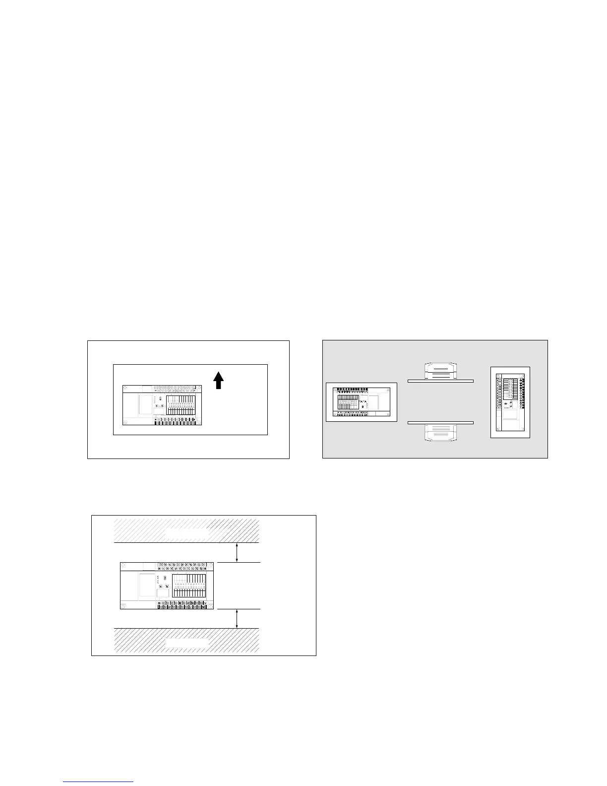
• When mounting a wiring duct, maintain a clearance between the unit and duct as shown in the figure.
(Illustration: FP1 Control Unit)
• The FP1 unit is wrapped in a protective sheet to prevent scraps and wire debris from getting inside. Please remove this
sheet when installation and wiring is finished.
• Do not install the unit as shown below.
(Illustration: FP1 Control Unit)
• Install as shown below, for heat radiating units.
(Illustration: FP1 Control Unit)
3-1. Installation