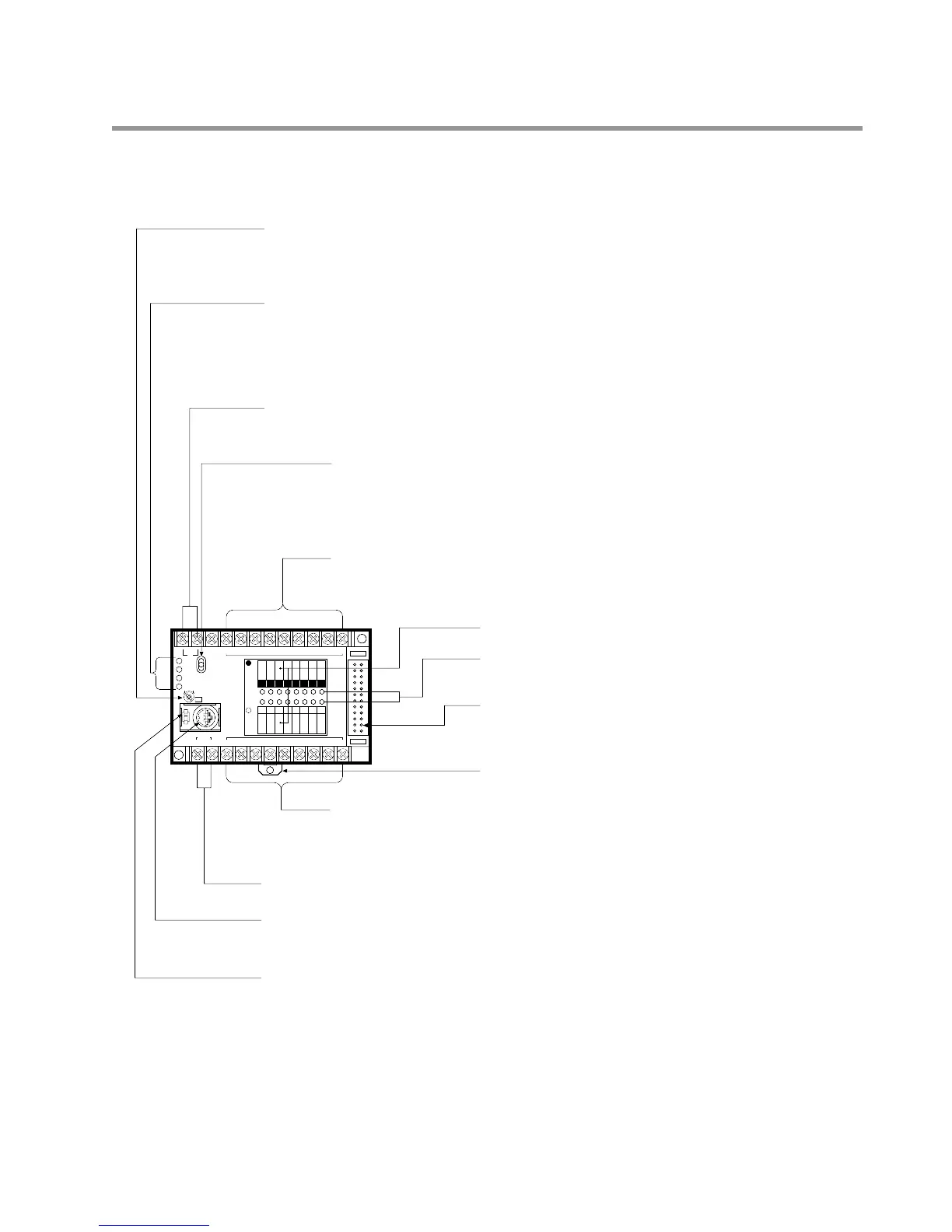
2-1. Parts Terminology and Functions
Programming Tools Connector (RS422 port):
Use this connector to connect the programming tools (e.g., FP Programmer II or personal computer with
NPST-GR Software) using the FP1 Peripheral Cable.
Baud Rate Selector:
Selects the baud rate for communication with a peripheral device (FP Programmer, FP Programmer II or
personal computer with NPST-GR Software).
Sets the baud rate selector according to the peripheral device to be connected to the RS422 port.
FP Programmer (AFP1112): 19,200 bps
FP Programmer (AFP1112A): 19,200 bps or 9,600 bps
FP Programmer II (AFP1114): 19,200 bps or 9,600 bps
Personal computer with NPST-GR: 9,600 bps
Potentiometer (V0):
Set with a screwdriver, the potentiometer allows you to manually adjust the controller. This feature lets
you input an analog value ranging from 0 to 255. The set value is stored in the manual dial-set register
(DT9040).
Operation Monitor LEDs:
RUN LED ON: when program is executed
Flashes: when forcing input/output is executed in RUN mode
PROG. LED ON: when the Control Unit halts program execution
ERR. LED ON: when a self-diagnostic error occurs
ALARM LED ON: when an abnormality is detected or watchdog timer error occurs
Mode Selector:
RUN mode: The Control Unit executes programs.
REMOTE mode: The mode (RUN mode or PROG. mode) can be changed using programming
tools (e.g., FP Programmer II and personal computer with NPST-GR Software).
PROG. mode: You can edit a program.
Power Supply Terminals:
• AC type Control Unit: power supply terminals for 100 V AC to 240 V AC
• DC type Control Unit: power supply terminals for 24 V DC
Output Terminals:
C14 series: 6 points, C16 series: 8 points
I/O Name Board
I/O State Indicators:
Indicates the input and output ON/OFF states.
Expansion Connector:
Connects to the FP1 Expansion Unit or FP1 Intelligent Unit (FP1
A/D Converter Unit or FP1 D/A Converter Unit) or FP1 I/O Link Unit.
See page 12 and 42.
DIN Rail Attachment Lever
Input Terminals:
C14 and C16 series: 8 points
Input voltage range: 12 V DC to 24 V DC
Built-in DC Power Output Terminals for Inputs (AC type only):
DC power for inputs can be supplied from these terminals. See page 45.