25
2-1. Parts Terminology and Functions
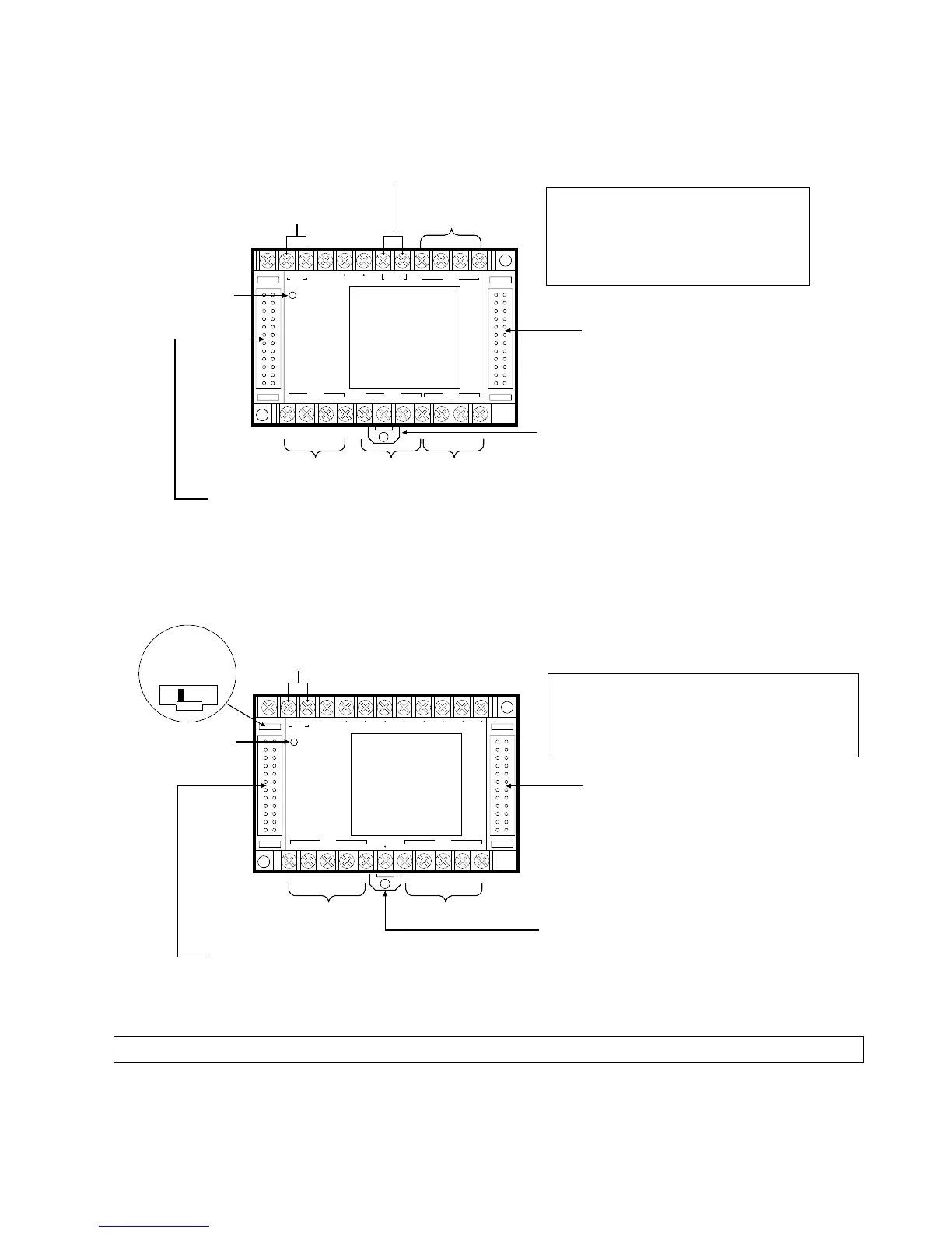
3. Intelligent Unit
1) FP1 A/D Converter Unit (Illustration: DC type)
2) FP1 D/A Converter Unit (Illustration: DC type)
Note:
• Terminals marked with “•” cannot be used as output terminals.
F.G.
RANGE
I0
+
FP1-2D/A
Matsushita
Erectric Works, Ltd.
FP1-003-93-B.b
Power
NAIS
+-
24V DC
V0
+
V0
-
V1
+
V1
-
I0
-
I1
-
RANGE I1
+
CH. 1CH. 0
Channel 0 Channel 1
Power Supply Terminals
DIN Rail Attachment Lever
Power Supply
LED
Unit Number
Selector
01
Expansion Connector (left side)
Connects to the FP1 Control Unit or FP1 Expansion Unit.
Expansion Connector (right side)
Connects to the FP1 Intelligent Unit
(FP1 A/D Converter Unit or FP1 D/A
Converter Unit) or FP1 I/O Link Unit.
• Terminals for Channel 1 and Channel 2
V+, V-:
RANGE:
I+, I-:
Analog voltage output terminals
Voltage range selection terminals
Analog current output terminals
F.G. V3 I3 C3 F.G.
C0
F.G.
FP1-4A/D
Matsushita
Erectric Works, Ltd.
FP1-003-93-B.a
Power
NAIS
+-
24V DC
CH. 3RANGE
V0 I0
C1
F.G.
V
1 I1
C2
V2 I2
CH. 2CH. 1CH. 0
Power Supply Terminals
DIN Rail Attachment Lever
Channel 3
Voltage Range Selection Terminal
Power Supply
LED
Expansion Connector (left side)
Expansion Connector (right side)
Connects to the FP1 D/A Converter
Unit or FP1 I/O Link Unit.
• Terminals for Channel 0 to Channel 3
V:
I:
C:
F.G:
Analog voltage input terminal
Analog current input terminal
Common terminal
Frame ground terminal
Connects to the FP1 Control Unit or FP1 Expansion Unit.
Channel 0
Channel 1 Channel 2
2-1. Parts Terminology and Functions