193
6-4. Hints for Programming High-level Instructions
2. How to Use Index Registers (IX, IY)
1) Index Registers (IX, IY)
• Each FP1 has two index registers available (IX and IY).
• The functions of index registers are classified into two types as follows:
- modifier of other operands
- memory area
■ When used as modifier of other operands
The index register can be used as a modifier for other operands (WX, WY, WR, SV, EV, DT, and constants K and H)
in the high-level and some basic instructions.
With this ability, a single instruction can control as if many instructions were programmed.
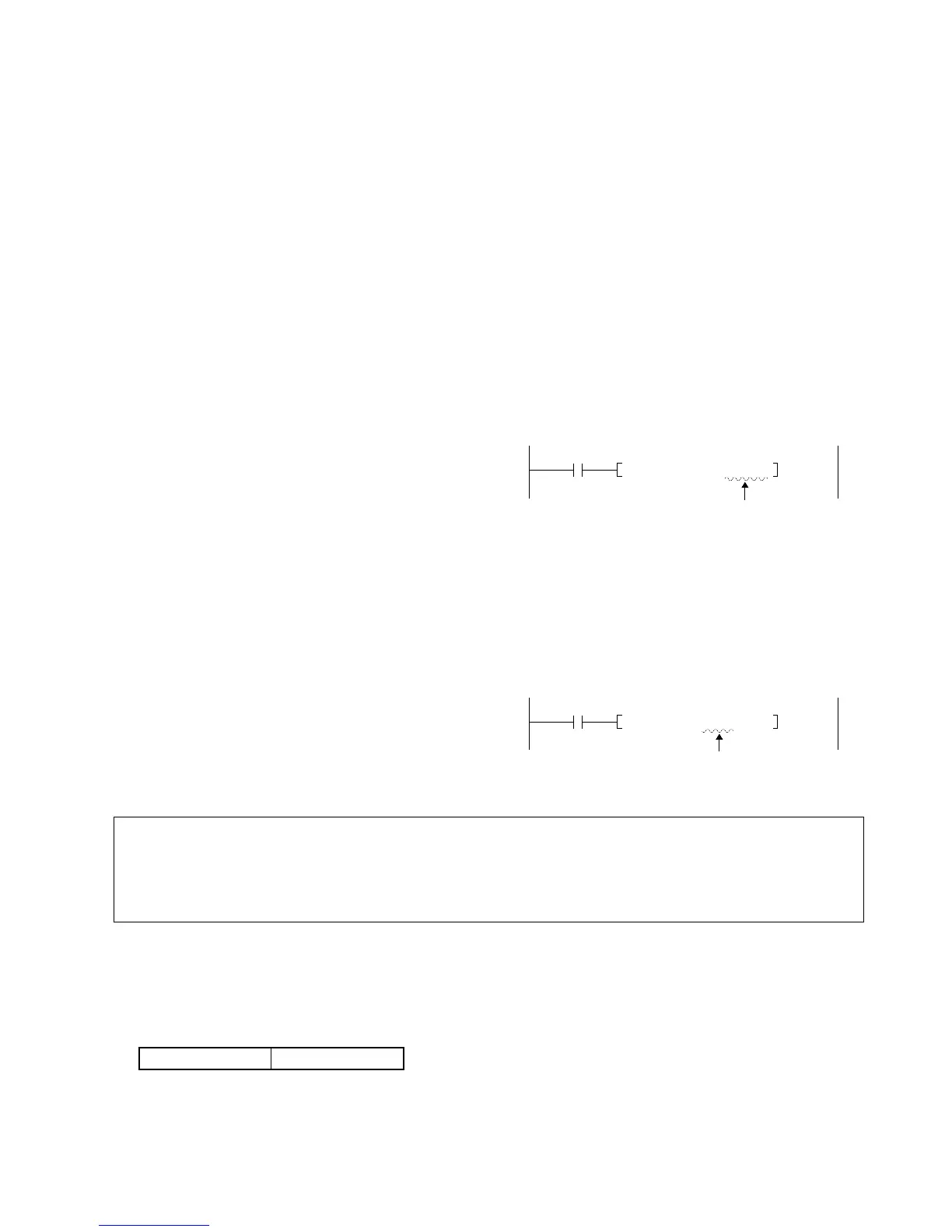
• Address modifier function (for WX, WY, WR, SV, EV, and DT)
When the index register is programmed together with another operand (WX, WY, WR, SV, EV, or DT), the address
of the original memory area is shifted as many times as the value in the index register (IX or IY).
When the index register is used as an address modifier, IX and IY work independently.
Example: When the data in the DT0 is transferred to a data register (DT) specified by the DT100 and the IX.
• Constant modifier function (for K and H)
When the index register is programmed together with a constant (K or H), the value in the index register is added to
the original constant value (K or H).
When the index register is used as a constant modifier, pay attention to the following:
- in the 16-bit instruction...IX and IY can be used independently.
- in the 32-bit instruction...IX is regarded as lower 16-bit and IY as higher 16-bit (only IX can be specified).
Example: The added result of K100 and the data in IY and IX is written to DT0.
Notes:
■ When used as memory area
• When the index registers are used as a 16-bit memory area, IX and IY work independently.
• When the index registers are used as a 32-bit memory area, IX is regarded as lower 16-bit and IY as higher 16-bit.
When programming it as a 32-bit operand, if you specify IX, IY is automatically specified as higher 16-bit.
• The index register cannot be modified with an index register.
• When the index register is used as an address modifier, be sure to check that the shifted address does
not exceed its last address. If the shifted address is beyond its last address, an operation error occurs
and the ERR. LED turns ON. For details about operation errors, refer to page 196, “3. Operation Errors”.
• When the index register is used as a constant modifier, the modified data may overflow or underflow.