EasyManuals Logo

NAiS FP1 User Manual

Default Icon
280 pages
To Next Page IconTo Next Page
To Previous Page IconTo Previous Page
Page #66 background imageLoading...
Page #66 background image
58
4-1. Operating Principles of the Programmable Controller
4-1. Operating Principles of the
Programmable Controller
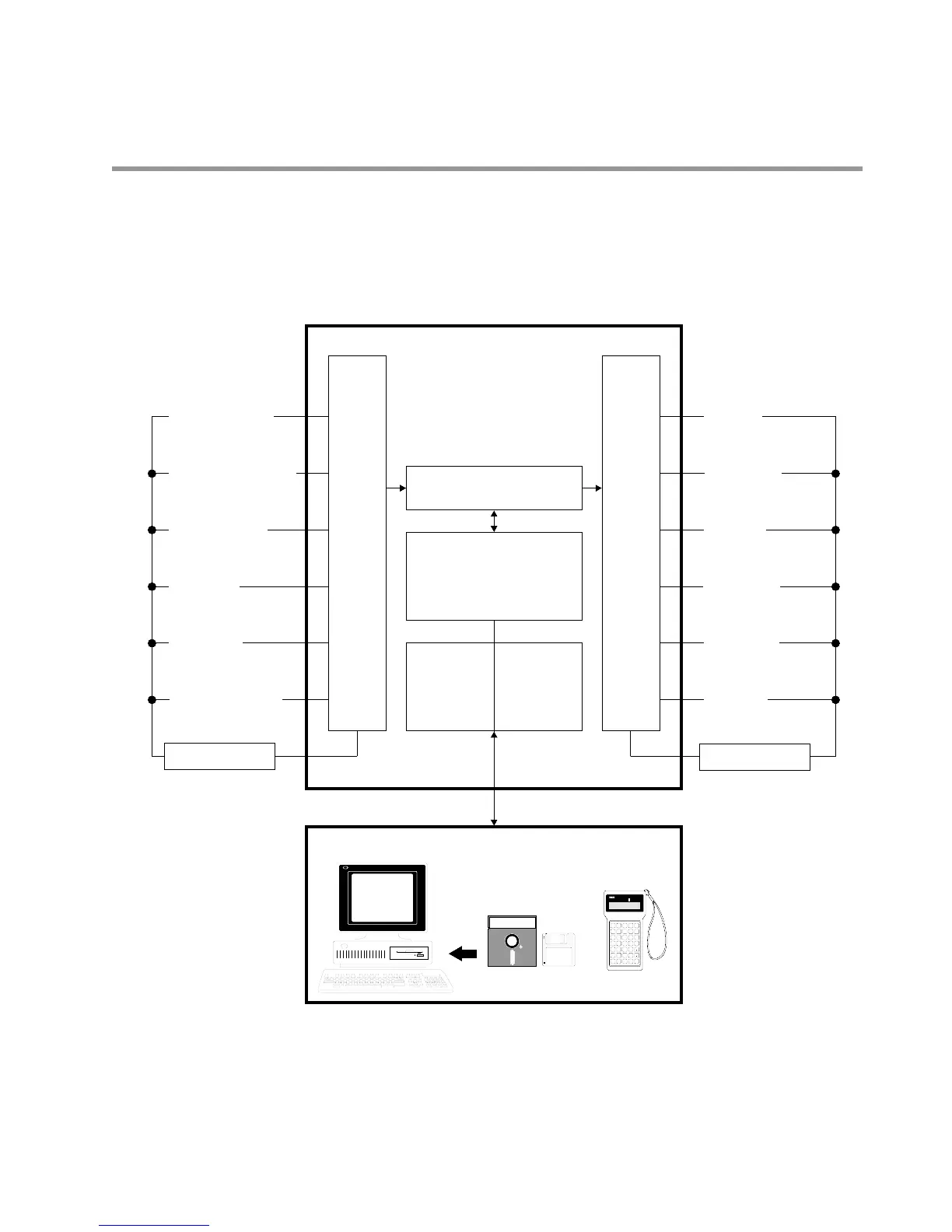
1. Basic Configuration
A programmable controller is composed of four basic sections: 1 CPU, 2 memory, 3 input interface, and 4
output interface. An inside look at these sections will help you understand their functions and operation of the
programmable controller.
NPST-GR Software
FP
Programmer II
Personal computer
Programming tools
Output field devices
Inverter
(variable speed
drive)
Segment
indicators
Indicators
Buzzers
Programmable Controller
Input field devices
Limit switches
Manual operating
switches
Photoelectric
sensors
Inductive
proximity switches
Encoders
Digital switches
Power supply
Relays
Solenoids
3
Input
inter-
face
4
Output
inter-
face
2-a
Memory for operand
1 CPU
(Central
Processing Unit)
2-b
System
register
2-c
Memory for
program
Power supply
FP PROGRAMMER
ST
X•WX
AN
Y•WY
OR
R•WR
OT
L•WL
FN/P
FL
NOT
DT/Ld
STK
IX/IY
TM
T•SV
CT
C•EV
(BIN)
K/H
=
C
D
D
<
E
>
F
SHIFT
SC
89AB
4 5 6 7
0 1 2 3
(
-
)
OP
SRC
READ
(HELP)
CLR
ACLR
(DELT)
INST
ENT
WRT

Table of Contents

Questions and Answers:

Question and Answer IconNeed help?

Do you have a question about the NAiS FP1 and is the answer not in the manual?

NAiS FP1 Specifications

General IconGeneral
BrandNAiS
ModelFP1
CategoryController
LanguageEnglish

Related product manuals