26
2-1. Parts Terminology and Functions
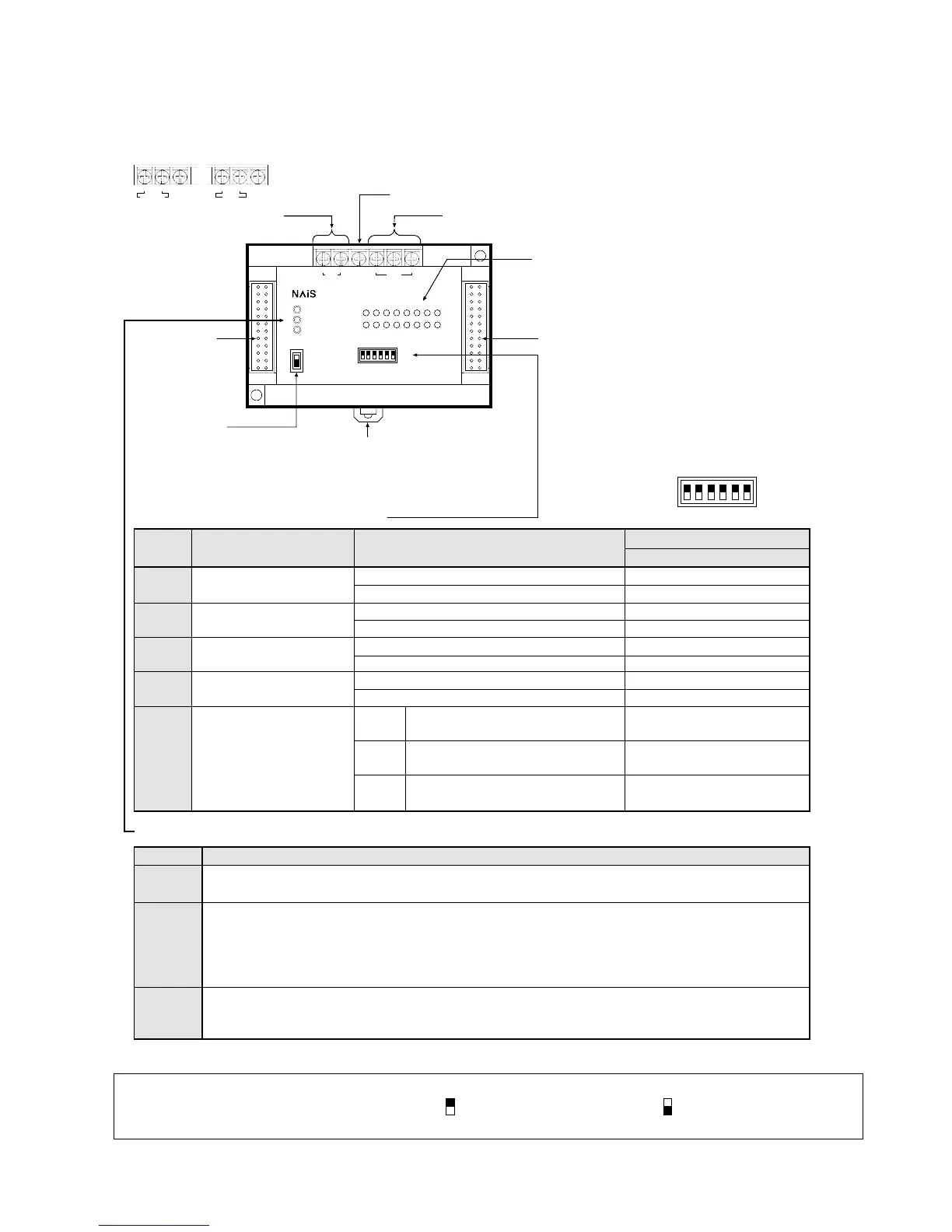
4. Link Unit
1) FP1 Transmitter Master Unit
Notes:
• The operation mode selectors are set to all OFF position when shipped.
• Operation mode selector upper state is “OFF( )” and the lower state is “ON ( )”.
• Be sure to power is OFF when changing the switch position.
Frame ground Terminal
DIN Rail Attachment Lever
POWER
COM.
ALARM
Station monitor LEDs
ON: Connected to the slave station
Flashing: Cased by a communication error
at this slave station number
OFF: Not connected to the slave station
RS485 Interface
Interface for MEWNET-TR communication using twisted pair cable
F.G. +-F.G.+-
24V DC
RS485
Selector
Number
Description
ON
OFF
Selector position
1 2 3 4 5 6
Remote I/O control disabled, Master B of I/O link
Remote I/O control enabled, Master A of I/O link
Start (continues I/O control operation)
Stop
Terminal station
Not a terminal station
ON when an I/O link error occurs
Not setting
Pattern
NO. 1
Pattern
NO. 2
Pattern
NO. 3
System configuration
selection
Output opration condition
during a communication error
Terminal station setting
Error flag (R9036) setting
I/O allocation setting
(use I/O address for
expansion board)
Operation mode selector setting
Descriptions
Power is supplied
Power is not supplied
Normal communication status (Flash in approx. 0.2 s intervals)
Not communicating
A communication error occurred at the slave station. The normal slave station
continues I/O control operation. (Flash in approx. 1 s intervals)
A communication error with a slave station
Station number setting error
Error on FP-M transmitter master board (MEWNET-TR)
Normal
ON:
OFF:
Flashing:
ON:
Flashing slowly:
OFF:
Flashing:
ON:
OFF:
Operation Monitor LEDs
LED
Expansion
Connector
Connected to the
FP1 Control Unit
using expansion
cable
TRNET
MODE SW.
ON
OFF
1
23456
Matsushita Electric Works, Ltd.
MONITOR SW.
INPUT UNIT
OUTPUT UNIT
0
7123456
8
F9ABCDE
Power supply terminal
(AC type/DC type)
Selector for
station monitor LEDs
(MONITOR SW.)
Selects the unit type (input or output)
of station monitor LEDs
"
"
"
Expansion Connector
Connects to the FP1 MEWNET-TR master unit
using expansion cable
Function
1
2
3
4
5 and 6
32 inputs:
32 outputs:
48 inputs:
32 outputs:
24 inputs:
16 outputs:
X70 to X8F
Y70 to Y8F
X30 to X47, X50 to X67
Y30 to Y3F, Y50 to Y5F
X30 to X47 or X50 to X67
Y30 to Y3F or Y50 to Y5F
ON
OFF
ON
OFF
ON
OFF
–
ON
OFF
OFF
ON
ON
POWER
COM.
ALARM
ON
OFF
1
23456
F.G. +-F.G.LN
100V - 240 VAC 240 V DC
AC type DC type