F.G. +-F.G.
FP1-003-93-B.c
+-
24V DC
RS485
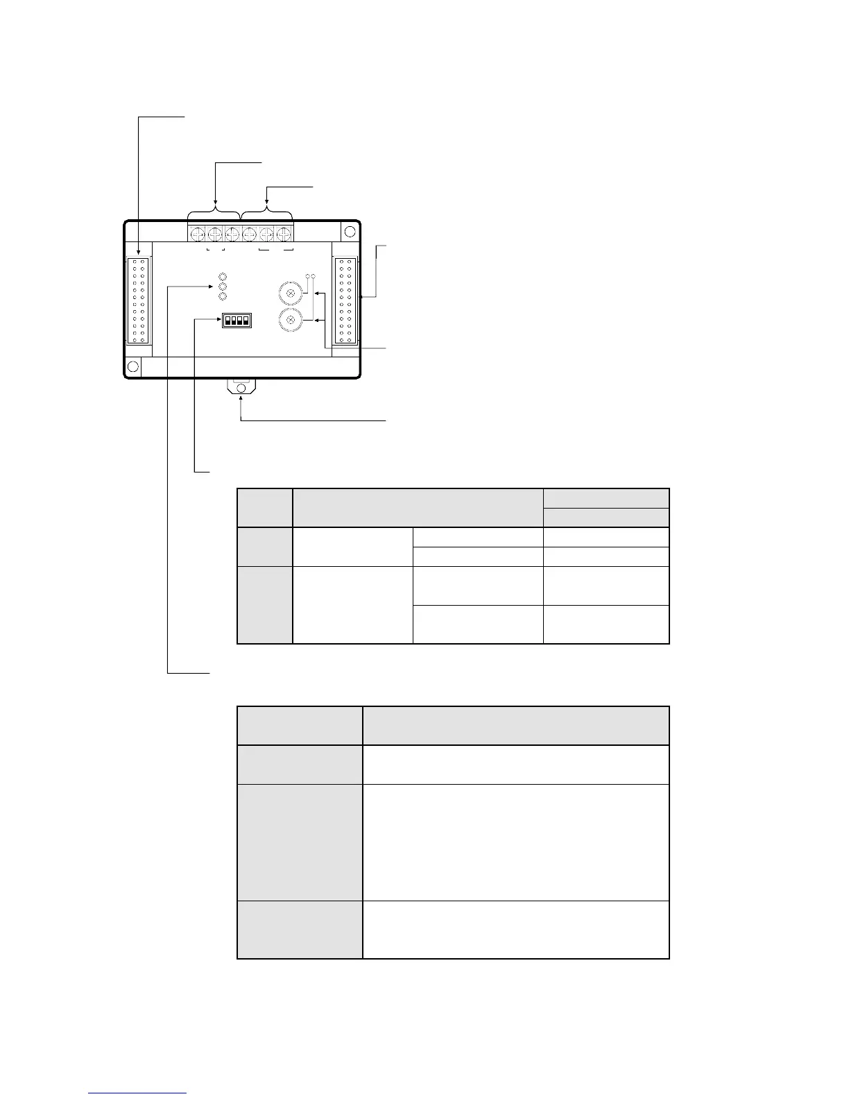
Power Supply Terminals (AC type/DC type)
DIN Rail Attachment Lever
0
1
2
3
4
5
6
7
8
9
0
1
2
3
4
5
6
7
8
9
STATION NO.
POWER
COM.
ALARM
PC
FP1
I/O LINK
MODE SW.
ON
OFF
1 234
Station Number Selector:
Set the slave station number
of the Remote I/O System.
Setting range: 01 to 32
Expansion Connector (right side)
Connects to the FP1 Intelligent Unit
(FP1 A/D Converter Unit or FP1 D/A
Converter Unit).
RS485 Interface
For connecting a communication cable.
Expansion Connector (left side)
Connects to the FP1 Control Unit or FP1 Expansion Unit.
Switch
Number
1 & 2
3
Specification
OFF OFF
ON ON
Switch position
1 2 3 4
Not a terminal station
Terminal station
Stop
Start (maintains its
output condition)
Terminal station
setting
Slave station output
condition during
a communication
error
OFF
ON
Mode Selector Switches
Power (POWER)
Communication
(COM.)
Alarm (ALARM)
Descriptions
When power is supplied
When power is not supplied
Not communicating
Communicating (Normal)
Remote I/O control halted,
caused by a communication
error at the slave station.
Abnormal condition
Unit error
Station number setting error
Normal unit
ON:
OFF:
ON:
Flashing:
Flashing slowly:
OFF:
ON:
Flashing:
OFF:
Operation Monitor LEDs
Indicate communication status and operation modes.
LED
"
"
"