45
3. Input Terminals of Control Unit and Expansion Unit
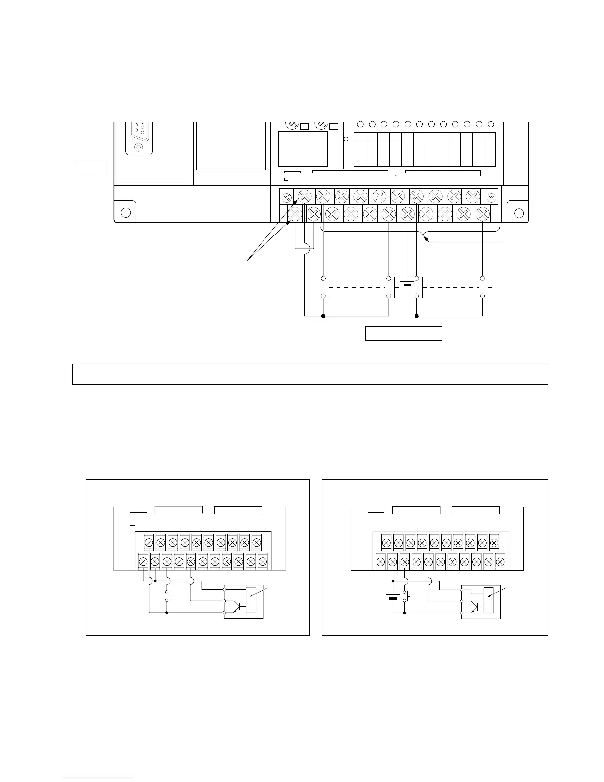
1) Wiring Example for Input Terminals
(Illustration: FP1 Control Unit)
Note:
2) Description
• Keep the input lines as far away from output lines as possible.
• Keep the input lines at least 100 mm/3.937 in. away from the motor and high voltage line.
• Refer to page 29, “1. General Specifications”, for details about built-in DC power output for inputs.
• Do not supply power from an exterior source to the built-in DC power output terminal (the part indicated as 24 V
DC+-) of AC type unit.
• Do not connect power supplies for inputs together in parallel, and do not connect to another power supply in
parallel.
• Refer to page 31, “2. Performance Specifications of Control Unit and Expansion Unit”.
• If the capacity of the DC type or the power output for
inputs are insufficient, use an exterior power supply.
• With the AC type, the built-in DC power output for
inputs can be used.
• Do not connect input devices to the input terminals indicated with a “•” symbol.