35
2-2. Specifications
3. Performance Specifications of Intelligent Unit
1) FP1 A/D Converter Unit
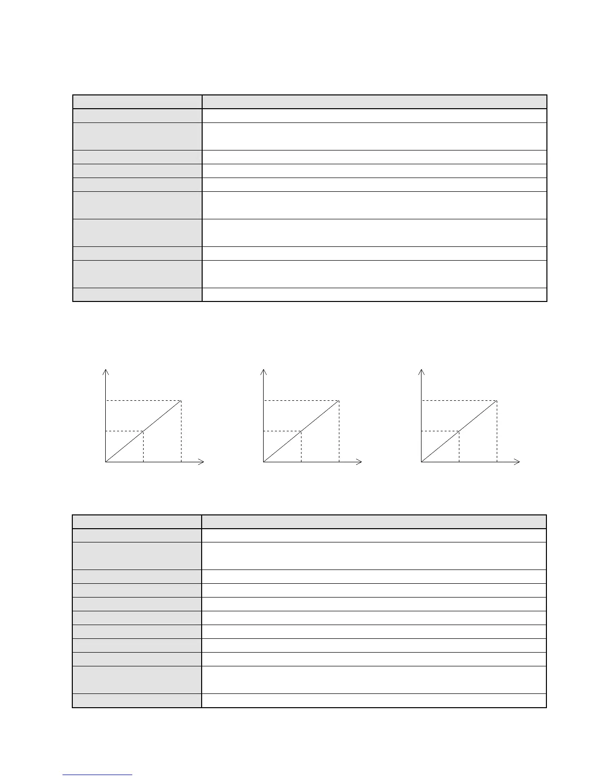
■ I/O Conversion Characteristics
2) FP1 D/A Converter Unit
Analog output points
Analog output range
Resolution
Overall accuracy
Response time
Output impedance
Maximum output current
Allowable load resistance
Digital output range
Insulation method
Connection method
2 channels/unit
0 to 5 V and 0 to 10 V
0 to 20 mA
1/1000
±1 % of full scale
2.5 ms/channel
0.5 Ω or less (at voltage output terminal)
20 mA (at voltage output terminal)
0 to 500 Ω (at current output terminal)
K0 to K1000 (H0000 to H03E8)
Optical coupler: between terminal and internal circuit
Not insulated: between channels
Terminal block (M 3.5 screw)
DescriptionItem
1000
500
2.5 5.0
Digital
output
Analog input
(K)
(V)
• 0 to 5 V range
1000
500
510
Digital
output
Analog input
(K)
(V)
• 0 to 10 V range
1000
500
10 20
Digital
output
Analog input
(K)
(mA)
• 0 to 20 mA range
000
Analog input points
Analog input range
Resolution
Overall accuracy
Response time
Input impedance
Absolute input range
Digital output range
Insulation method
Connection method
4 channels/unit
0 to 5 V and 0 to 10 V
0 to 20 mA
1/1000
±1 % of full scale
2.5 ms/channel
1 MΩ or more (at 0 to 5 V and 0 to 10 V range)
250 Ω (at 0 to 20 mA range)
+7.5 V (at 0 to 5 V range), +15 V (at 0 to 10 V range)
+30 mA (at 0 to 20 mA range)
K0 to K1000 (H0000 to H03E8)
Optical coupler: between terminal and internal circuit
Not insulated: between channels
Terminal block (M 3.5 screw)
DescriptionItem