EasyManua.ls Logo

NAiS FP1

Default Icon
280 pages
To Next Page IconTo Next Page
To Previous Page IconTo Previous Page
Loading...
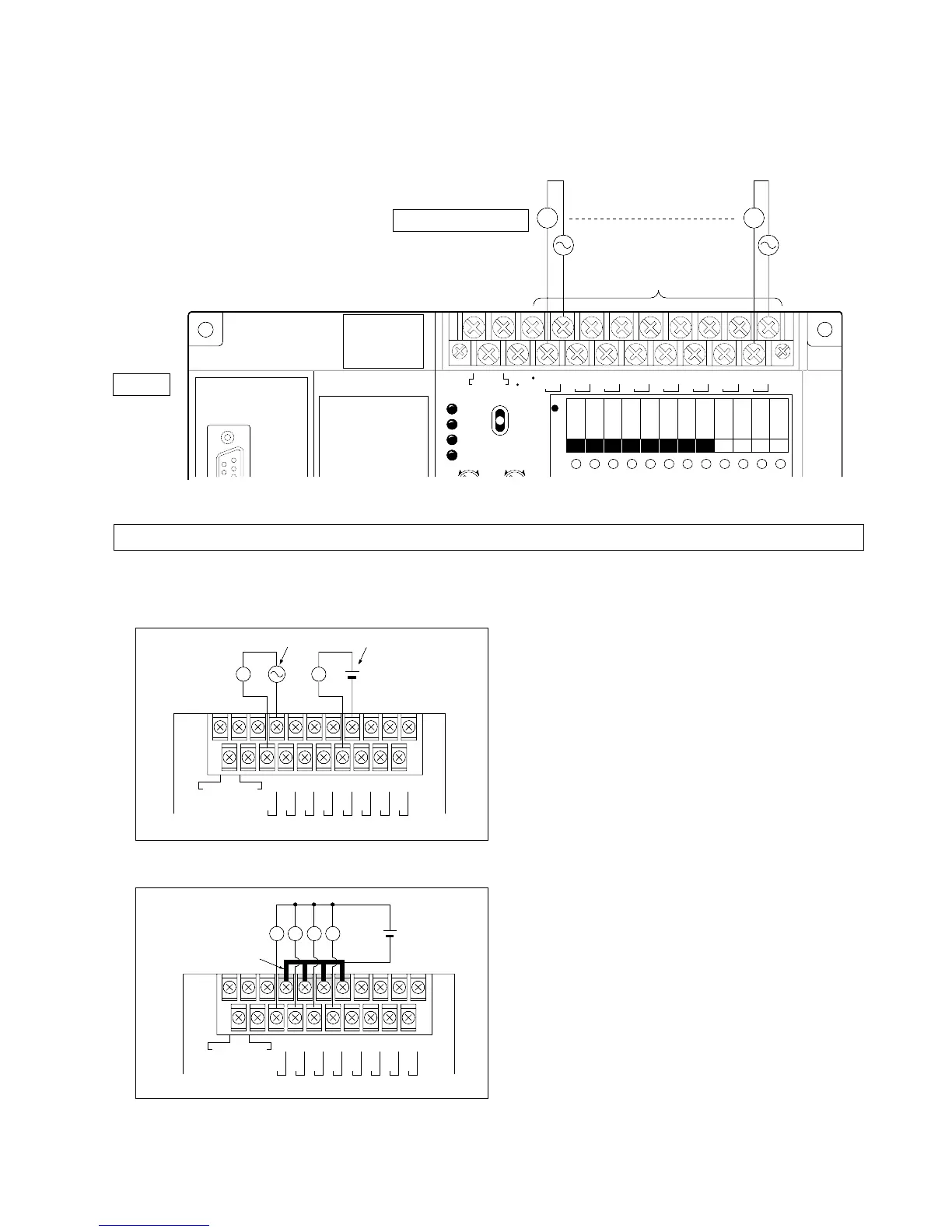
4. Output Terminals of Control Unit and Expansion Unit
1) Wiring Example for Output Terminals
(Illustration: FP1 Control Unit)
Note:
2) Description
• A different voltage can be used with each independent common.
• When more than one loade is connected to the same power supply, short the COM terminal with the short-circuit
bar (Part number AFP1803).
• Refer to page 33, “3) Output Specifications of Control Unit and Expansion Unit”, for details about output
specifications.
0
100-240 V AC
COM
1
COM
2
COM
3
COM
4
COM
5
COM
6
COM
7
COM
F.G.
LLLL
FP1-040-93-B
Short-circuit bar
0
100-240 V AC
COM
1
COM
2
COM
3
COM
4
COM
5
COM
6
COM
7
COM
F.G.
AC power supply DC power supply
FP1-039-93-B
LL
• Do not connect output devices to the output terminals indicated with a “•” symbol.
COM
0
COM
1
COM
2
COM
3
COM
4
COM
5
COM
6
COM
7
100 240 V AC
F.G.
RUN
REMOTE
PROG.
max.
min.
RUN
PROG.
ERR.
ALARM
BATTERY
max.min.
01234567CDEF
OUTPUT
Y
(24V DC)
Output devices
Output terminals
AC AC
LM
FP1-038-93-B
Unit
49
3-3. Wiring

Table of Contents

Related product manuals