EasyManuals Logo

NAiS FP1 User Manual

Default Icon
280 pages
To Next Page IconTo Next Page
To Previous Page IconTo Previous Page
Page #167 background imageLoading...
Page #167 background image
159
6-3. Description of High-level Instructions
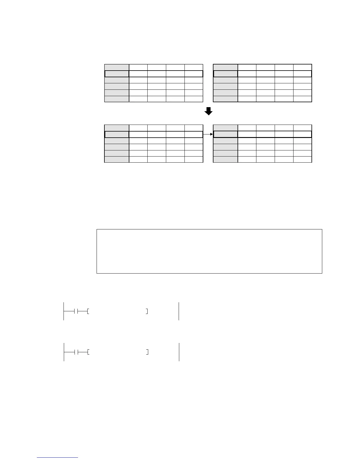
Description
• The 16-bit data or 16-bit equivalent constant specified by S is copied to the area specified by D
when the trigger turns ON.
Flag condition
• Error flag (R9007): Turns ON and keeps the ON state when the area specified using the index
modifier exceeds the limit. The error address is transferred to DT9017
and held. (See notes below.)
• Error flag (R9008): Turns ON for an instant when the area specified using the index modifier
exceeds the limit. The error address is transferred to DT9018. (See notes
below.)
Notes:
Application example
Example 1: Put the value of the dial set register in the timer set value area.
Example 2: Transfer the timer elapsed value EV0 to the data register DT0 when X2 turns ON.
0
X2
F0 MV, EV0, DT0
0
R9010
F0 MV, DT9040, SV0
R9010: Always ON special internal relay
DT9040: Manual dial set register for "V0"
Special data registers DT9017 and DT9018 are available only for FP1s with CPU
version 2.7 or later. (All FP1s with a sufx B on the part number have this function.)
When using special internal relay R9008 as the flag for this instruction, be sure to
program the flag at the address immediately after the instruction.
Refer to page 223, 8-3. Table of Special Internal Relays, for details about error
flags.
Bit position
WX0
WX1
WX2
WX3
WX4
11 8
1010
1100 1010
1110
30
Source
Trigger X0: ON
15 ••12 •• ••
74
••
0000
0000 0000
0010
0000
0000 0000
0011
0000
0000 0000
0100
0000
0000 0000
0101
[S]
Bit position
WR0
WR1
WR2
WR3
WR4
11 8
0000
0000 0000
1111
30
Destination
15 ••12 •• ••
74
••
0000
0000 0000
1110
0000
0000 0000
1101
0000
0000 0000
1100
0000
0000 0000
1011
[D]
Bit position
WX0
WX1
WX2
WX3
WX4
11 8
1010
1100 1010
1110
30
Source
15 ••12 •• ••
74
••
0000
0000 0000
0010
0000
0000 0000
0011
0000
0000 0000
0100
0000
0000 0000
0101
[S]
Bit position
WR0
WR1
WR2
WR3
WR4
11 8
1010
1100 1010
1110
30
Destination
15 ••12 •• ••
74
••
0000
0000 0000
1110
0000
0000 0000
1101
0000
0000 0000
1100
0000
0000 0000
1011
[D]

Table of Contents

Questions and Answers:

Question and Answer IconNeed help?

Do you have a question about the NAiS FP1 and is the answer not in the manual?

NAiS FP1 Specifications

General IconGeneral
BrandNAiS
ModelFP1
CategoryController
LanguageEnglish

Related product manuals