43
3-3. Wiring
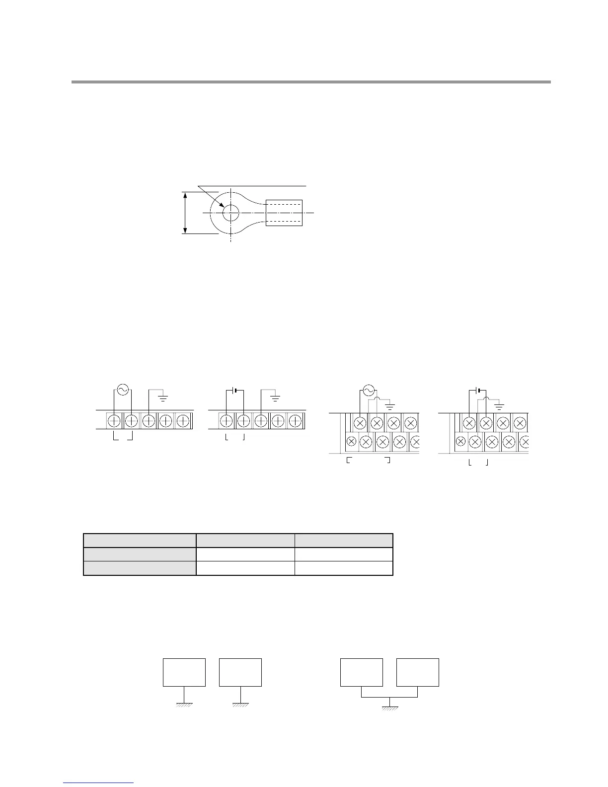
1. Crimp Terminal
• M3.5 screws are used for the I/O terminal block.
• Use of crimp terminals is recommended for wiring to the terminals.
• Be sure to connect the cables and the interface terminals correctly using crimp terminals.
• Suitable crimp terminals are ring terminals, insulated ring terminals and fork terminals.
2. Wiring Power Supply
1) Wiring Example for Power Supply Terminal
• Operating power is not required for E8 and E16 series Expansion Units.
■ Operating Voltage
■ Grounding
• The FP1 has sufficient noise resistance under low noise level conditions. However, ground the FP1 unit for safety.
• When grounding, an earth-ground resistance of 100 Ω or less is recommended to limit the effect of noise due to
electromagnetic interference.
• Do not use a grounding wire that is shared with other devices.
• FP1 Control Unit (C24, C40, C56, and C72 series)
FP1 Expansion Unit (E24 and E40 series)
• FP1 Control Unit (C14 and C16 series),
FP1 A/D Converter Unit, FP1 D/A Converter
Unit, and FP1 I/O Link Unit