160
6-3. Description of High-level Instructions
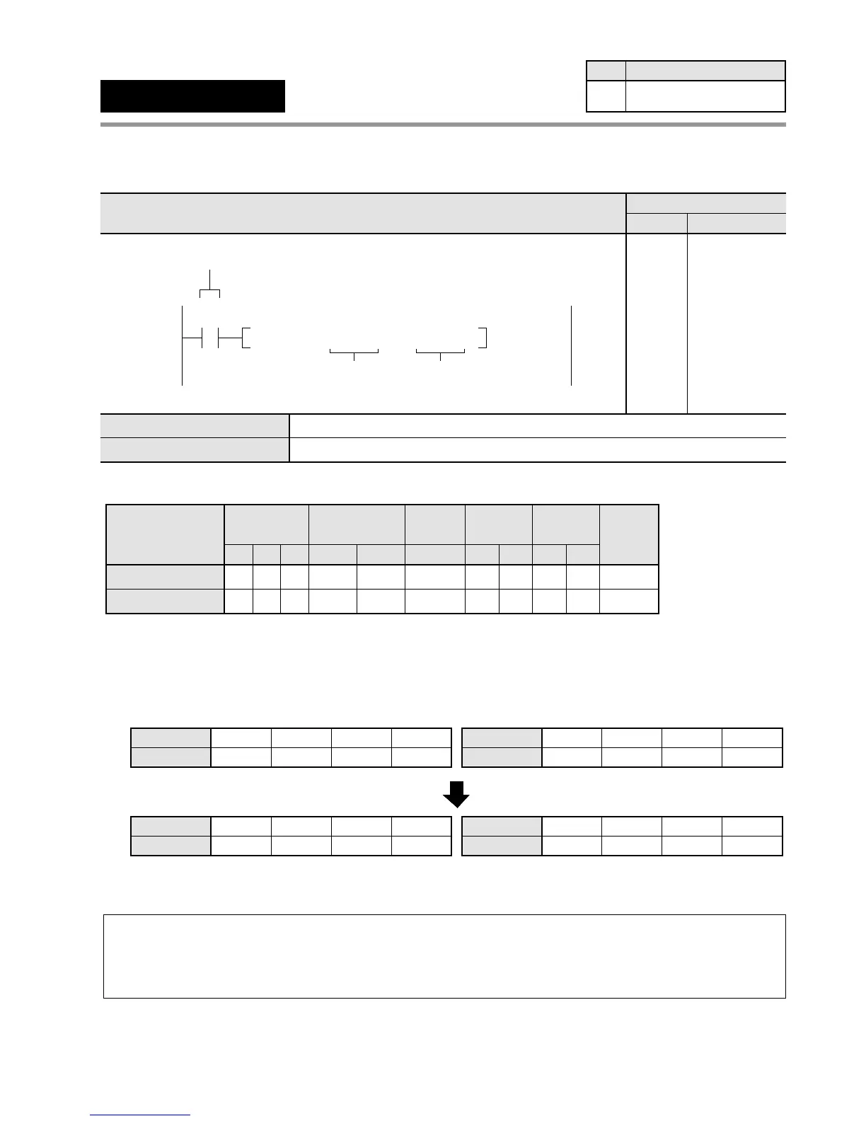
Outline Copies the 32-bit data to the specified 32-bit area.
Program example
■ Operands
■ Explanation of example
• The contents of word internal input relays WR1 and WR0 are copied to data registers DT1 and DT0 when trigger
X0 turns ON.
Note:
• When processing 32-bit data, the higher 16-bit areas (S+1, D+1) are automatically decided if the lower
16-bit areas (S, D) are specified.
e.g., S+1 (higher) = WR1, S (lower) = WR0
D+1 (higher) = DT1, D (lower) = DT0
Bit position
WR1
1010
1100
11 8
1010
1110
30
Source [S+1, S]: HACAEE486
X0: ON
15
••12 •• ••
74
••
Bit position
DT1
1010
1100
11 8
1010
1110
30
Destination [D+1, D]: HACAEE486
15 ••12 •• ••
74
••
Bit position
WR0
1110
0100
11 8
1000
0110
30
15 ••12 •• ••
74
••
Bit position
DT0
1110
0100
11 8
1000
0110
30
15 ••12 •• ••
74
••
"
"
"
"
"
"
"
"
"
"
"
"
"
"
"
"
"
"
"
higher 16-bit area
"
"
"
"
"
"
"
"
"
"
"
"
"
"
"
"
"
"
"
higher 16-bit area
"
"
"
"
"
"
"
"
"
"
"
"
"
"
"
"
"
"
"
lower 16-bit area
"
"
"
"
"
"
"
"
"
"
"
"
"
"
"
"
"
"
"
lower 16-bit area
F1
(DMV)
32-bit data move
Availability
Step
7 All series
S
D
32-bit equivalent constant or lower 16-bit area of 32-bit data (source)
Lower 16-bit area for 32-bit data (destination)
Ladder Diagram
Boolean Non-ladder
Address Instruction