116
5-3. Description of Basic Instructions
Description
• The TM instruction is a down type preset timer.
• If there are not enough TM instruction numbers, you can increase the number by changing the
setting of system register 5. Refer to page 230, “8-5. System Registers”, for details on how to
change the number of timer instructions.
■ Timer set time
The formula of the timer set time is [the time unit] × [set value]
Example: TMX5 K30 (0.1 s × 30 = 3 s)
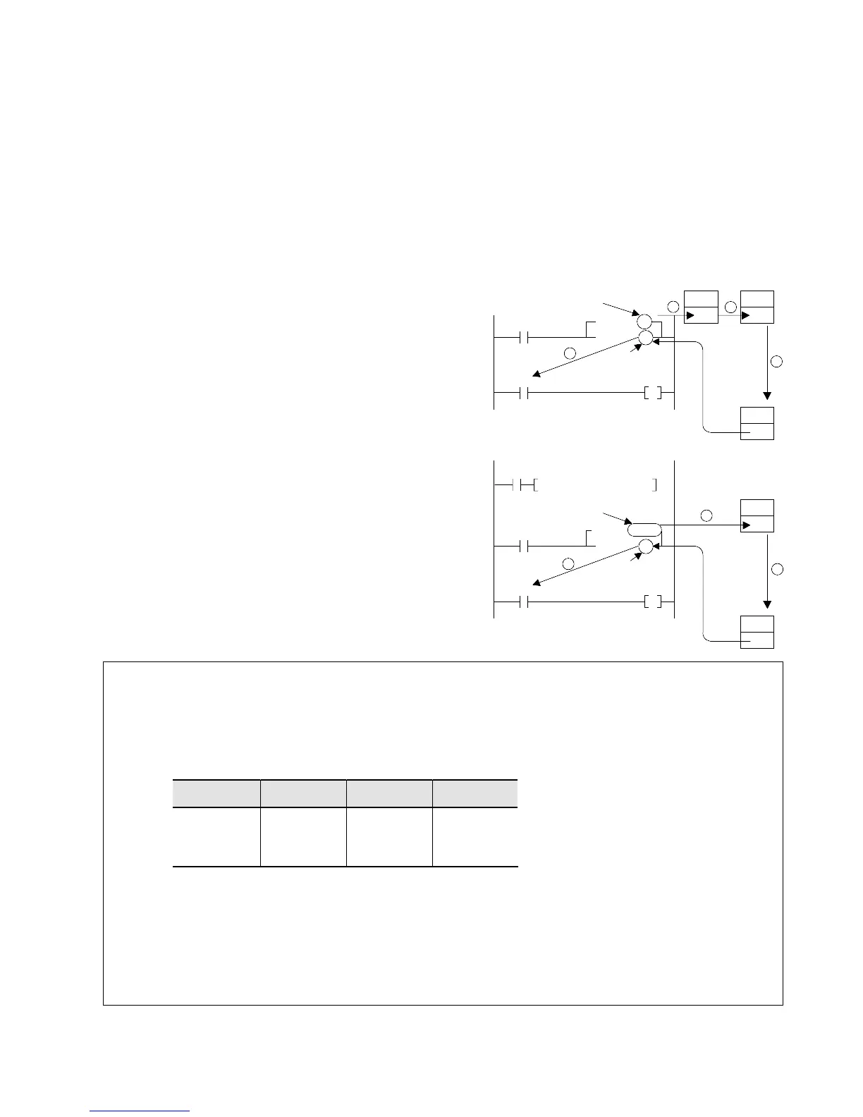
■ Timer operation
• When the decimal constant “K” is specified as a set value:
Procedure:
1 When the mode of the programmable controller is set to
RUN, K30 (decimal) is transferred to set value area SV5.
2 When the leading edge of trigger X0 is detected (OFF →
ON), set value K30 is transferred from the SV5 to the
elapsed value area EV5.
3 The passed time is subtracted from the EV5 every scan
while trigger X0 is in the ON state.
4 When the data in the elapsed value area EV5 becomes 0,
timer contact T5 turns ON and then the Y0 goes ON.
• When the “SVn” is specified as a set value:
Procedure:
1 When the leading edge of trigger X0 is detected (OFF →
ON), the value in set value area SV5 is transferred to the
elapsed value area EV5.
2 The passed time is subtracted from the EV5 every scan
while trigger X0 is in the ON state.
3 When the data in elapsed value area EV5 becomes 0, timer
contact T5 turns ON and then Y0 goes ON.
Notes:
• If you turn OFF timer operation trigger X0 in the middle of an operation, the operation will be interrupted
and the elapsed time will be reset to 0.
• Timer set value area SV is a memory area for the timer’s time setting.
• The timer contact goes ON when the value in timer elapsed value area EV becomes 0. However, the
value in timer elapsed value area EV will also become 0 in a reset condition.
• For each TM instruction, one SV and EV set and one contact T are supported as follows:
• The timer is reset whenever the power is turned OFF, or the mode is changed from RUN to PROG. Set
system register 6 to retain the run status.
Refer to page 232, “2. Table of System Registers”, for details about system registers.
• Since the timing operation is executed during the scan of the timer instruction, program timer instructions
so that the TM instruction is executed once per scan.
Be sure that the TM instruction is executed once per scan when the INT, JP, LOOP instructions and
others are programmed.