6
1-1. Features
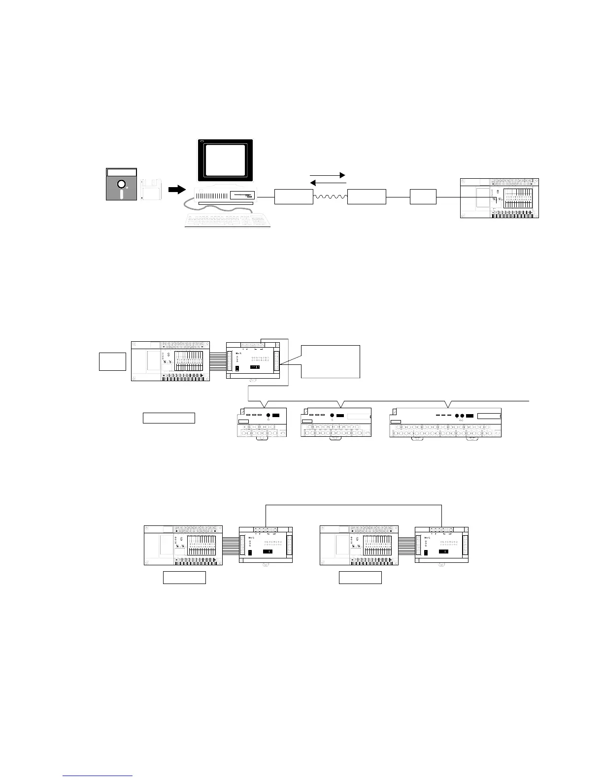
■ Modem communication (C24, C40, C56, and C72 series)
Using a modem, data transfer and long-distance communication between a personal computer and an FP1 unit can
be performed. This can be done even when using NPST-GR Software. Select a cable in accordance with the
specifications of the modem used.
■ MEWNET-TR (Remote I/O Control) system
I/O information can be exchanged between a master and several slave stations at a remote site. A maximum of 80
inputs and 64 outputs can be controlled by 2 master units (C24, C40, C56 and C72 series) one transmitter master
unit supports a total communication distance of 700 m using twisted pair cable. Master to master communication is
also available.
• Master-slave communication
• Master-master communication
COM
0
COM
1
COM
2
COM
3
COM
4
COM
5
COM
6
COM
7
+-
24V DC
F.G.
COM
F
8
9
EA
B
C
D
(+)
-
COM
7
0
1
62
3
4
5
(+)
-
RUN
REMOTE
PROG.
V0
max.
min.
RUN
PROG.
ERR.
ALRAM
BATTERY
V1
max.
PC
FP1-C24
24V DC
+
-
min.
FP1 Control Unit
F.G. +-F.G.+-
24V DC
RS485
POWER
COM.
ALARM
TRNET
MODE SW.
ON
OFF
1
23456
Matsushita Electric Works, Ltd.
MONITOR SW.
INPUT UNIT
OUTPUT UNIT
0
7123456
8
F9ABCDE
FP1 Transmitter
Master Unit
Master A
COM
0
COM
1
COM
2
COM
3
COM
4
COM
5
COM
6
COM
7
+-
24V DC
F.G.
COM
F
8
9
EA
B
C
D
(+)
-
COM
7
0
1
62
3
4
5
(+)
-
RUN
REMOTE
PROG.
V0
max.
min.
RUN
PROG.
ERR.
ALRAM
BATTERY
V1
max.
PC
FP1-C24
24V DC
+
-
min.
FP1 Control Unit
F.G. +-F.G.+-
24V DC
RS485
POWER
COM.
ALARM
TRNET
MODE SW.
ON
OFF
1
23456
Matsushita Electric Works, Ltd.
MONITOR SW.
INPUT UNIT
OUTPUT UNIT
0
7123456
8
F9ABCDE
FP1 Transmitter
Master Unit
Master B
Twisted pair cable or 2-conductor cable
COM
0
COM
1
COM
2
COM
3
COM
4
COM
5
COM
6
COM
7
+-
24V DC
F.G.
COM
F
8
9
EA
B
C
D
(+)
-
COM
7
0
1
62
3
4
5
(+)
-
RUN
REMOTE
PROG.
V0
max.
min.
RUN
PROG.
ERR.
ALRAM
BATTERY
V1
max.
PC
FP1-C24
24V DC
+
-
min.
FP1 Control Unit
F.G. +-F.G.+-
24V DC
RS485
POWER
COM.
ALARM
TRNET
MODE SW.
ON
OFF
1
23456
Matsushita Electric Works, Ltd.
MONITOR SW.
INPUT UNIT
OUTPUT UNIT
0
7123456
8
F9ABCDE
FP1 Transmitter Master Unit
I/O Transmitter
Unit (4-point)
Master
station
Slave stations
NAIS FP I/O TRANSMITTER UNIT
4-OUTPUT (T1 O.5 A NPN) AFP87527
ab ab ab ab
Matsushita
Electronic Works, Ltd
POWER COM. ALARM
TRNET
I/O Transmitter
Unit (8-point)
I/O Transmitter
Unit (16-point)
Max. 700 m with twisted pair cable
NAIS FP I/O TRANSMITTER UNIT 16-OUTPUT (T1 O.5 A NPN) AFP87524
ab ab ab ab ab ab ab ab ab ab ab ab ab ab ab ab
Matsushita Electronic Works, Ltd
POWER COM. ALARM
TRNET
NAIS FP I/O TRANSMITTER UNIT 8-INPUT (24 V DC) AFP87521
ab ab ab ab ab ab ab ab
Matsushita Electronic Works, Ltd
POWER COM. ALARM
TRNET
When shipped,
32 inputs
32 output
FP1 Control Unit
COM
0
COM
1
COM
2
COM
3
COM
4
COM
5
COM
6
COM
7
+-
24V DC
F.G.
COM
F
8
9
EA
B
C
D
(+)
-
COM
7
0
1
62
3
4
5
(+)
-
RUN
REMOTE
PROG.
V0
max.
min.
RUN
PROG.
ERR.
ALARM
BATTERY
V1
max.
PC
FP1-C24
24V DC
+
-
min.
Personal computer
NPST-GR Software
Modem Modem
Public telephone line
RS422/232C
Adapter