148
6-1. Configuration of High-level Instructions
■ Word external input relay (WX), Word external output relay (WY)
and Word internal relay (WR)
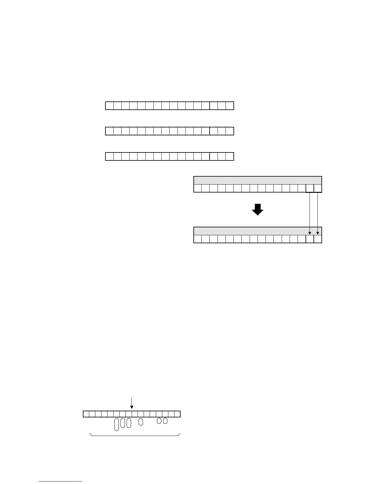
• “WX”, “WY” and “WR” express the relays (X, Y and R). This word format treats the 16-bit relay groupings as one
word.
• The word relay addresses (WX, WY and WR) can also be expressed by bit addresses using X, Y, and R, as
follows.
Example: Word external input relay (WX)
• The contents of the word relay correspond to the state of its relays (components).
■ Hold and non-hold settings of the data register (DT)
• The terms “hold” and “non-hold” are specified as;
Hold area: the memory area whose contents will not be lost or modified if the operating power is lost or
if the mode of the programmable controller is changed from RUN to PROG.
Non-hold area: the memory area whose contents will be lost or modified if the operating power is lost or if
the mode of the programmable controller is changed from RUN to PROG.
• Settings of “hold” or “non-hold” for the data register (DT) can be performed by changing the setting in system
register 8.
Refer to page 230, “8-5. System Registers”, for details about the settings of hold type and non-hold types.
• The default value in system register 8 is “0” and all the data registers (DT) are set as hold type.
■ Constant (Decimal and Hexadecimal)
Decimal constant(K constant)
• Use of the decimal constant is most common and it is mainly used to input data to the programmable controllers.
Some data such as the timer/counter set (preset) value should be programmed using this decimal constant.
The decimal constant is expressed by adding the prefix “K” to the data.
• The decimal constant input to the FP1 is converted internally to binary and then processed.
Example: When K1868 (decimal) is input to the FP1.
When the data of WR0 is K0 (decimal), if R0
and R1 are turned ON, its data becomes K3
(decimal). In the same way, if the data of WR0
is changed from K0 to K3, this means that R0
and R1 are turned ON.
 Loading...
