171
Outline Subtracts the 32-bit data from the minuend and stores the result in the
specified area.
Program example
■ Operands
■ Explanation of example
• Subtracts the contents of data registers DT201 and DT200 from the contents of data registers DT101 and DT100
when trigger X0 turns ON. The subtracted result is stored in data registers DT1 and DT0.
Bit position
DT201
0000
0000
11 8
0000
1000
30
Subtrahend [S2+1, S2]: K525312
X0: ON
15
••12 •• ••
74
••
Bit position
DT1
0000
0000
11 8
1111
1000
30
Result [D+1, D]: K16284672
15 ••12 •• ••
74
••
Bit position
DT200
0000
0100
11 8
0000
0000
30
15 ••12 •• ••
74
••
Bit position
DT0
0111
1100
11 8
0000
0000
30
15 ••12 •• ••
74
••
"
"
"
"
"
"
"
"
"
"
"
"
"
"
"
"
"
"
"
higher 16-bit area
"
"
"
"
"
"
"
"
"
"
"
"
"
"
"
"
"
"
"
higher 16-bit area
"
"
"
"
"
"
"
"
"
"
"
"
"
"
"
"
"
"
"
lower 16-bit area
"
"
"
"
"
"
"
"
"
"
"
"
"
"
"
"
"
"
"
lower 16-bit area
Bit position
DT101
0000
0001
11 8
0000
0000
30
Minuend [S1+1, S1]: K16809984
15 ••12 •• ••
74
••
Bit position
DT100
1000
0000
11 8
0000
0000
30
15 ••12 •• ••
74
••
"
"
"
"
"
"
"
"
"
"
"
"
"
"
"
"
"
"
"
higher 16-bit area
"
"
"
"
"
"
"
"
"
"
"
"
"
"
"
"
"
"
"
lower 16-bit area
–
Timer/Counter
EV
Relay
SVWRWYWX
Operand
S1
AAA A
A:
N/A: Not Available
Register
DT
A
IYIX
A N/A
HK
AA
Constant
Index
modifier
A
Index
register
Available
A
S2
A A A A A A N/A A A AA
N/A A A A A A N/A N/A N/A AA
D
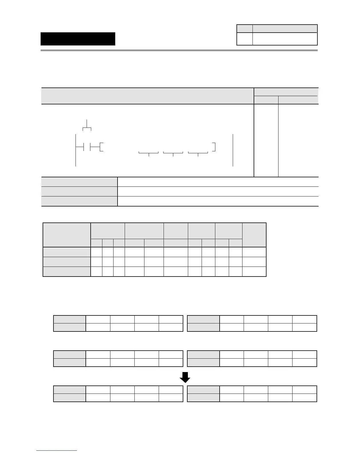
F28
(D–)
32-bit data
[(S1+1, S1) – (S2+1, S2) → (D+1, D)]
Availability
Step
11 All series
6-3. Description of High-level Instructions
32-bit equivalent constant or lower 16-bit area of 32-bit data (for minuend)
32-bit equivalent constant or lower 16-bit area of 32-bit data (for subtrahend)
Lower 16-bit area of 32-bit data (for result)
Ladder Diagram
Boolean Non-ladder
Address Instruction
20
X0
F28 D– , DT100 DT200 , DT 0
D
Trigger
S2S1
20
21
ST X 0
F28(D– )
DT 100
DT 200
DT 0
S1
S2
D
 Loading...
