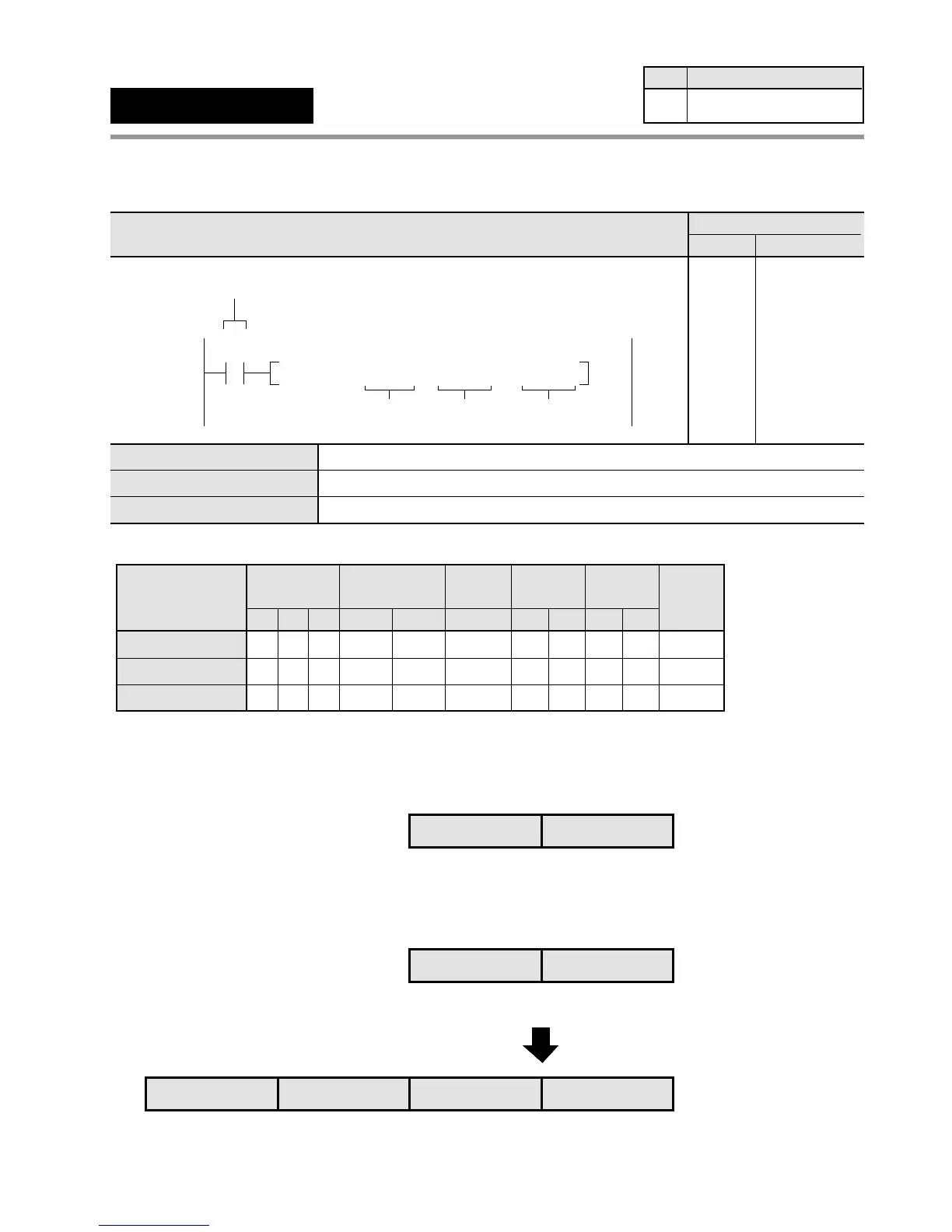
Outline Multiplies two 32-bit data and stores the result in the specified 64-bit area.
Program example
■ Operands
■ Explanation of example
• Multiplies the contents of data registers DT1 and DT0 and the contents of data registers DT101 and DT100 when
trigger X0 turns ON. The multiplied result is stored in data registers DT203, DT202, DT201, and DT200.
X0: ON
Multiplicand [S1+1, S1]: K1638411
"
"
"
"
"
higher 16-bit area
lower 16-bit area
+
DT101 DT100
DT201 DT200DT203 DT202
DT1 DT0
"
"
"
"
"
Multiplier [S2+1, S2]: K458761
Result [D+3, D+2, D+1, D]: K751639068771
"
"
"
"
"
higher 16-bit area
lower 16-bit area
"
"
"
"
"
Timer/Counter
EV
Relay
SVWRWYWX
Operand
S1
AAA A
A:
N/A: Not Available
Register
DT
A
IYIX
A N/A
HK
AA
Constant
Index
modifier
A
Index
register
Available
A
S2
A A A A A A N/A A A AA
N/A A A A A N/A N/A N/A N/A AA
D
6-3. Description of High-level Instructions
F31
(D
✽
)
32-bit data [(S1+1, S1) × (S2+1, S2)
→ (D+3, D+2, D+1, D)]
Availability
Step
11
C24, C40, C56,
and C72 series
32-bit equivalent constant or lower 16-bit area of 32-bit data (for multiplicand)
32-bit equivalent constant or lower 16-bit area of 32-bit data (for multiplier)
Lowest 16-bit area of 64-bit data (for result)
Ladder Diagram
Boolean Non-ladder
Address Instruction
10
X0
F31 D✽ , DT 0 , DT 100 , DT 200
D
Trigger
S2S1
10
11
ST X 0
F31(D✽ )
DT 0
DT 100
DT 200
S1
S2
D
175
 Loading...
