182
Description
• Compares the 16-bit data specified by S1 with one specified by S2 when the trigger turns ON.
The compared result is stored in special internal relays R9009, and R900A to R900C.
■ Flag condition
• Error flag (R9007): Turns ON and keeps the ON state when the area specified using the index
modifier exceeds the limit. The error address is transferred to DT9017
and held. (See notes below.)
• Error flag (R9008): Turns ON for an instant when the area specified using the index modifier
exceeds the limit. The error address is transferred to DT9018. (See notes
below.)
• The following table lists the conditions of carry flag (R9009), > flag (R900A), = flag (R900B),
and < flag (R900C), depending on the relative sizes of S1 and S2.
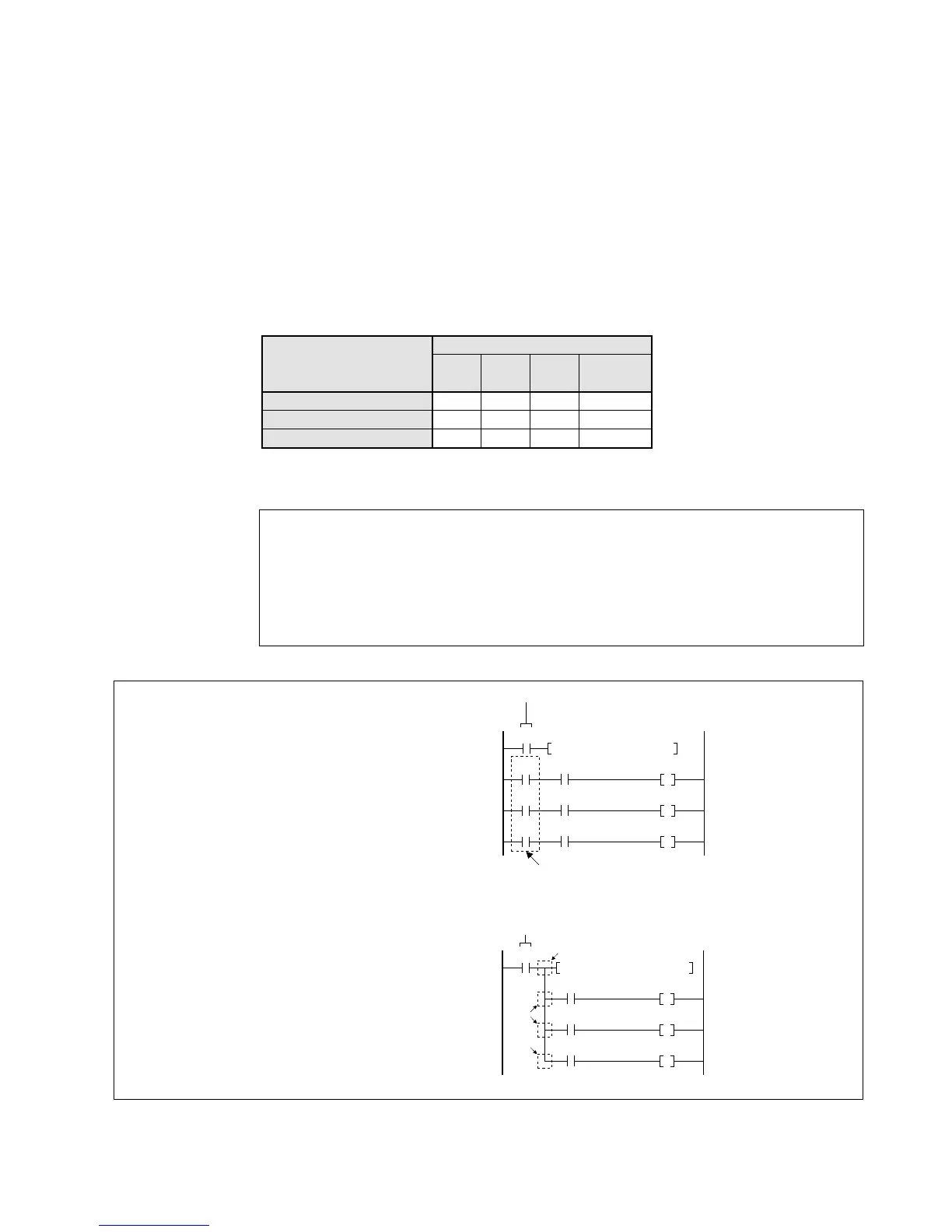
Notes:
Notes:
• Do not forget to program the same trigger as the
instruction to get the accurate comparison result.
Even if special relays are also programmed in
other parts of the program, the trigger prevents the
result of the other instruction from affecting them.
• You can also program the above using the PSHS,
RDS, and POPS instructions.
• Special data registers DT9017 and DT9018 are available only for FP1s with CPU
version 2.7 or later. (All FP1s with a suffix “B” on the part number have this function.)
• When using special internal relays R9008, R9009, R900A, R900B and R900C as
the flags for this instruction, be sure to program the flags at the address immediately
after the instruction.
• Refer to page 223, “8-3. Table of Special Internal Relays”, for details about error
flags.