ENGINE
03-M-E3B, 03-M-DI-E3B, 03-M-E3BG, WSM
1-S58
(Continued)
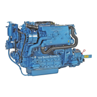
(When reassembling)
• Set the small governor spring (4) first and then the large
governor spring (3) on the speed control plate (6).
• Put the specific tool (1) from the injection pump side to catch the
large governor spring (3). Keep this spring in an extended
position and put the speed control plate (6) in its specified
position.
• Use the specific tool (1), set the small governor spring (4) on the
fork lever (2).
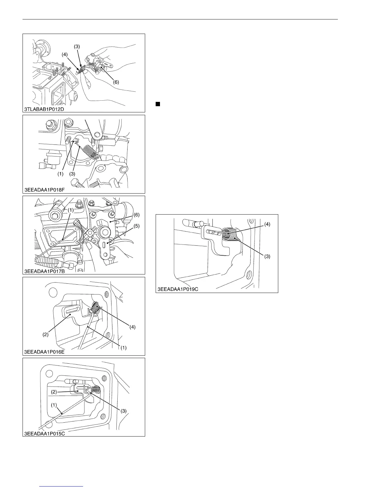
• Do not stretch the small governor spring (4) too much
because it can cause permanent deformation.
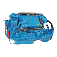
• Set the large governor spring (3) on the fork lever (2) with
the specific tool.
• Make sure that the 2 governor springs (3), (4) are tight on
the fork lever (2).
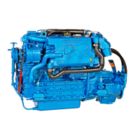
• Tighten the 2 bolts and 2 nuts on the speed control plate
(6).
• After you assemble the governor springs, make sure that
the speed control lever (5) is at the low-idle position.
• After you move the speed control lever (5) to the maximum
speed position, make sure that it goes back to the high-idle
position.
• Attach the injection pump cover in position.
M00000003ENS0081US1
(1) Specific Tool
(2) Fork Lever
(3) Large Governor Spring
(4) Small Governor Spring
(5) Speed Control Lever
(6) Speed Control Plate