ENGINE
03-M-E3B, 03-M-DI-E3B, 03-M-E3BG, WSM
1-S28
(4) Fuel System
Injection Timing
[D1503-M, D1703-M, D1803-M, V2003-M, V2203-M, V2403-M,
V2403-M-T, D1703-M-BG, V2003-M-BG, V2003-M-T-BG,
V2203-M-BG, V2403-M-BG]
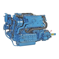
1. Remove the solenoid.
2. Remove the injection pipes and the glow plugs.
3. Set the speed control lever to the position of maximum fuel
discharge.
(Reference)
• Turn the flywheel with a screwdriver.
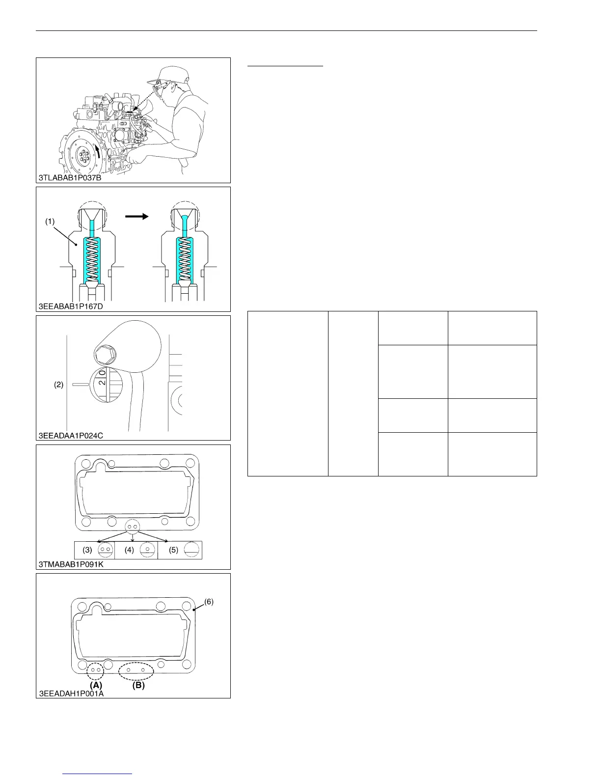
4. Turn the flywheel counterclockwise (refer to the figure) until the
fuel comes to the hole of the delivery valve holder for the first
cylinder.
5. Turn the flywheel more and stop when the fuel starts to flow out,
to get the injection timing.
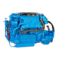
6. Calculate the angle at which the center of the window points out.
(The flywheel has a mark 1TC and 4 lines that shows every
0.09 rad (5 °) of crank angle from 0.17 rad (10 °) to 0.44 rad
(25 °) before mark 1TC.)
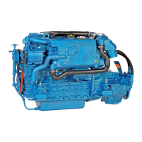
7. If the result is different from specified injection timing, add or
remove the shim to adjust.
(To be continued)
Injection timing
Factory
spec.
D1503-M,
V2003-M-T-BG
0.253 to 0.279 rad
(14.5 to 16.0 °) before
T.D.C.
D1703-M,
D1803-M,
V2003-M,
V2203-M,
V2403-M
0.271 to 0.296 rad
(15.5 to 17.0 °) before
T.D.C.
V2403-M-T
0.132 to 0.157 rad
(7.55 to 9.05 °) before
T.D.C.
D1703-M-BG,
V2003-M-BG,
V2203-M-BG,
V2403-M-BG
0.236 to 0.261 rad
(13.5 to 15.0 °) before
T.D.C.
(1) Delivery Valve Holder
(2) Timing Mark
(3) 2-Holes : 0.20 mm (0.0079 in.) Shim
(4) 1-Hole : 0.25 mm (0.0098 in.) Shim
(5) Without Hole : 0.30 mm (0.012 in.)
Shim
(6) 2-Holes : 0.175 mm (0.00689 in.)
Shim
(A) 3 Cylinder
(B) 4 Cylinder