E2600 Controller-Drive Tray Installation Guide 71
7. To attach the shorter, adjustable size mounting rails to the cabinet, perform these sets of substeps:
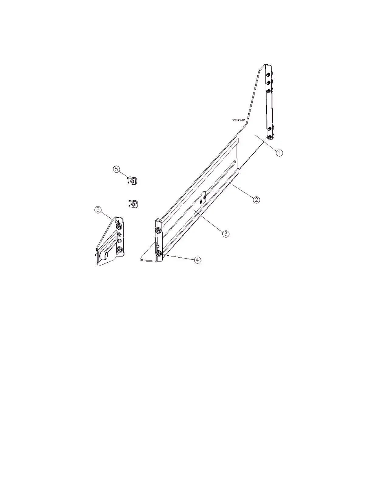
Figure 64 Short Adjustable Mounting Rail -- Left Side
1. Front of the Mounting Rail
2. Rear of the Mounting Rail
3. Rail Fix Bar
4. Two M5 Screws for the Front EIA Support Rail
5. Two Clips for the Front EIA Support Rail
6. Rear Bracket
a. Make sure that the adjustment screws on the mounting rail are loose so that the mounting rail can
extend or contract as needed (see the figure "Short Adjustable Mounting Rail -- Left Side").
b. Place the mounting rail inside the cabinet, and extend the mounting rail until the flanges on the
mounting rail touch the inside of the cabinet (see the figure "Short Adjustable Mounting Rail Attached
to the Cabinet" on page 72).
c. Insert one M5 screw through the front of the cabinet, and screw it into the top captured nut in the
mounting rail.
d. Insert two M5 screws through the rear of the cabinet, and screw them into the captured nuts in the
rear flange in the mounting rail.
e. Tighten the adjustment screws on the mounting rail.
f. Repeat substep a through substep e to install the second mounting rail.