Chapter 8: Hardware Installation for Synchronous Mirroring 203
Switch Zoning for
the Campus
Configuration
The campus configuration allows for a separate zone for each reserved port for the
Synchronous Mirroring premium feature.
The switches do not need to be zoned exactly as presented in this configuration.
However, you must meet the following requirements when you zone switches for the
campus configuration.
NOTE Do not zone the uplink ports (E_ports) on any of the Fibre Channel switches.
You must have a total of four zones in this configuration.
All zones exist on fabric 1 (switch 1A at the primary site, and switch 1B at the
secondary site).
Zone 3 and zone 4 are reserved for the dedicated Synchronous Mirroring
premium feature connections.
You must configure the zones on the switches so that there is
one port per zone for a
storage array connection and one port per zone for each host.
You must zone the switches so that a single host adapter can access only one
controller per storage array.
The switches in the following figure contain 16 ports each, which leaves many
unused ports per switch. The remaining ports can be distributed among the other
zones. However, it is recommended that most remaining ports be assigned to the
zones that contain the host connections (zone 1). This setup allows connections for
additional hosts.
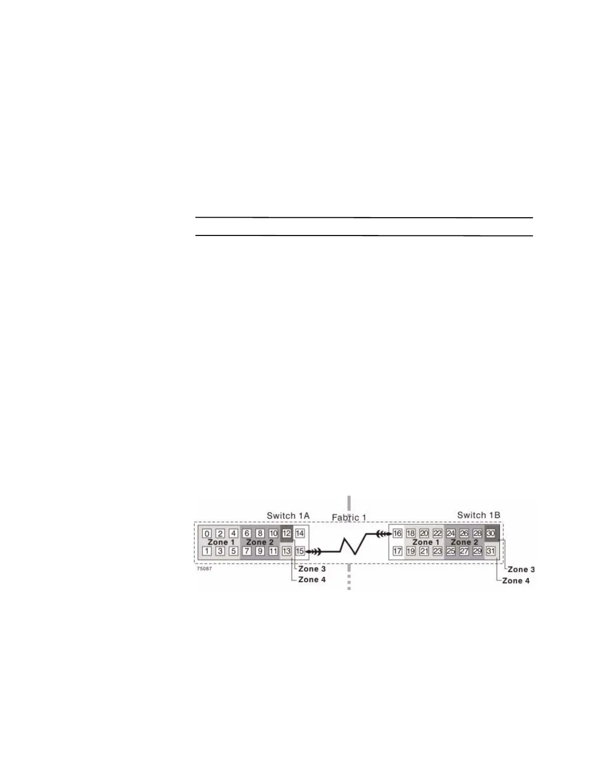
The following figure shows how the two switches are zoned for the campus
configuration.
Figure 8 Switch Zoning for the Ca
mp
us Configuration
Review the requirements in this section and the zoning example in the figure above to
make sure that both switches are correctly zoned before proceeding. For more
information, see "Switch Zoning Overview" on page 190.