22
Connecting to Drive
Trays That Support
Loop Switch
Technology
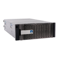
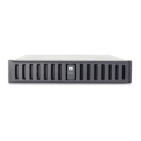
The FC2610 drive trays and the FC4600 drive trays operate internally as an array of
drives that are connected in a point-to-point configuration by a Fibre
Channel-Arbitrated Loop (FC-AL) loop switch. These drive trays are referred to as a
Switched Bunch of Disks (SBOD). Drive trays without loop switch support operating
as a string of drives on an arbitrated loop. SBOD drive trays operate more reliably
than drive trays that use a traditional loop configuration. The loop switch also reduces
transfer latency, which can increase performance in some configurations. To operate
in Switch mode, you must cluster SBOD drive trays together when they are combined
with other types of drive trays in a storage array topology.
The SBOD drive trays operate in Switch mode either when an SBOD drive tray is
connected singly to a controller tray or a controller-drive tray, or when multiple
SBOD drive trays are connected in series to a controller tray or a controller-drive tray.
An SBOD drive tray operates in Hub mode when a single SBOD drive tray is
connected in series with other drive trays that do not support a loop switch. The
SBOD drive trays also operate in Hub mode when multiple SBOD drive trays are
interspersed in series with other drive trays that do not support a loop switch. The
SBOD drive tray does not take advantage of the internal switch technology when
operating in Hub mode. Some statistics that are available in switch mode are not
available in Hub mode.
If SBOD drive trays are not clustered together correctly, the SANtricity ES Storage
Manager software shows a Needs Attention status for the SBOD drive trays. A Needs
Attention status does not prevent the SBOD drive trays from processing data;
however, the Needs Attention status persists until you change the cabling topology.
To maximize the performance of SBOD drive trays, always connect the SBOD drive
trays in a series.
The following figure shows a simple block diagram of three recommended topologies
for SBOD drive trays. All three scenarios shown in the figure are arranged to
maximize performance. The scenario on the left of the figure (all SBODs) also offers
the advantage of flexible drive connection; for example, connecting two In ports or
two Out ports. This flexible approach to drive connection is enabled by the FC-AL
feature.
In the figure, the FC2610 drive trays or the FC4600 drive trays are identified as
SBODs. The AT2655 drive trays are identified as SATA (Serial Advanced
Technology Attachment).
NOTE When you connect drive trays to the CE7922 controller tray or the CE7900
controller tray, you must not mix different types of drive trays on the same loop.