Chapter 3: Host Connection 51
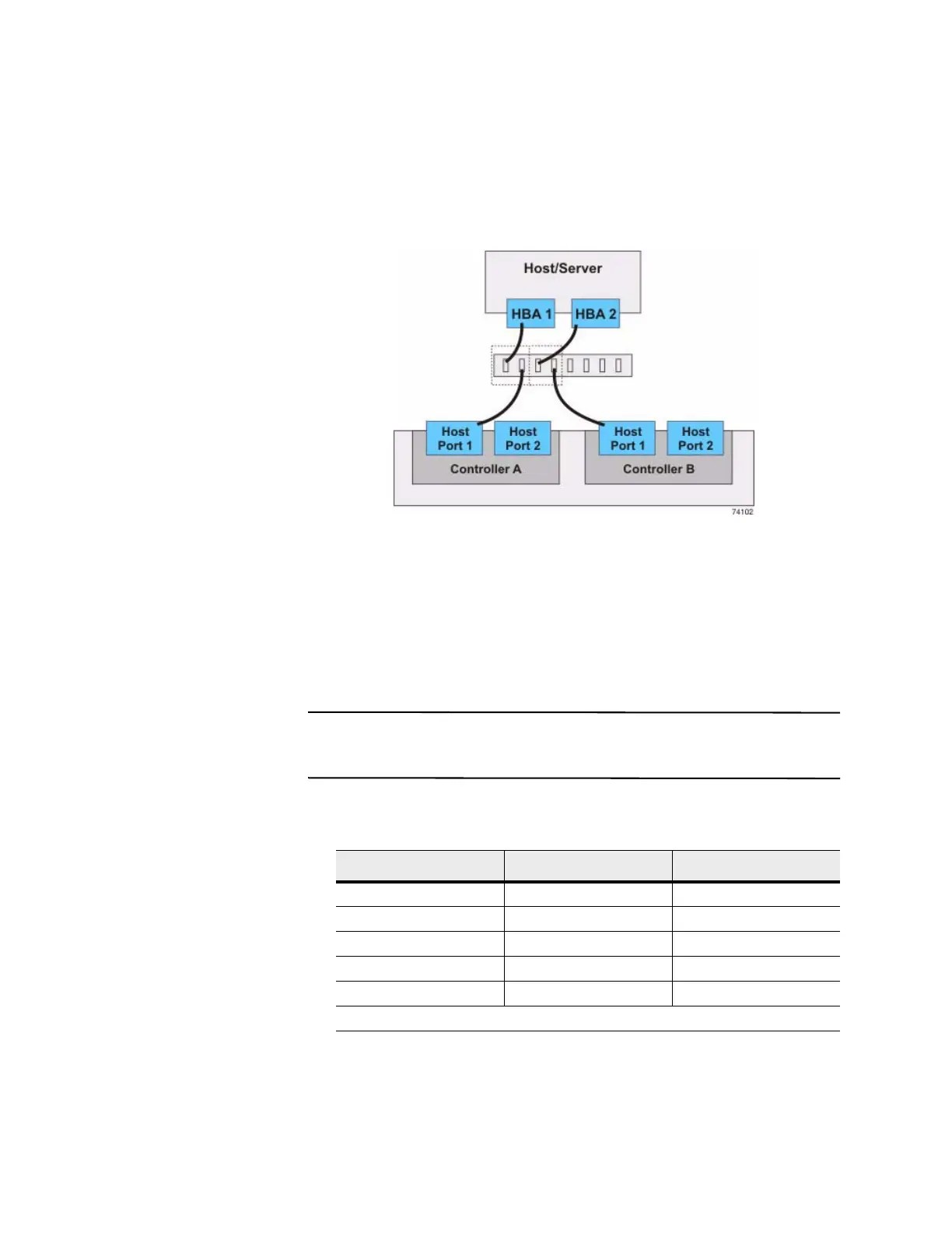
In the following figure, each outlined group of ports represents a zone.
Figure 5 Switch Topology – One Host and a Controller Tray or a
Contro
ller-Drive Tray with a Switch
Two Hosts to a
Controller Tray or a
Controller-Drive
Tray
The following figure shows an example of a switch topology with two hosts, a
controller tray or a controller-drive tray, and a zoned switch. The following table
describes which of the components in this topology are non-redundant and present a
risk of a single point of failure.
ATTENTION Possible loss of data access – You must install alternate path software
or an alternate path (failover) driver on the host to support failover in the event of an
HBA failure or a host channel failure.
Table 9 Redundant and Non-Redundant Components in a Switched
Configuration with Two Hosts and a Controller Tray or a Controller-Drive Tray
Component Redundant Non-Redundant
Host/server (see note) Redundant
Host adapter Redundant
Host-to-controller cable Redundant
Switch Non-redundant
Controller Redundant
Note – The hosts/servers in this example must be clustered to be redundant.