14
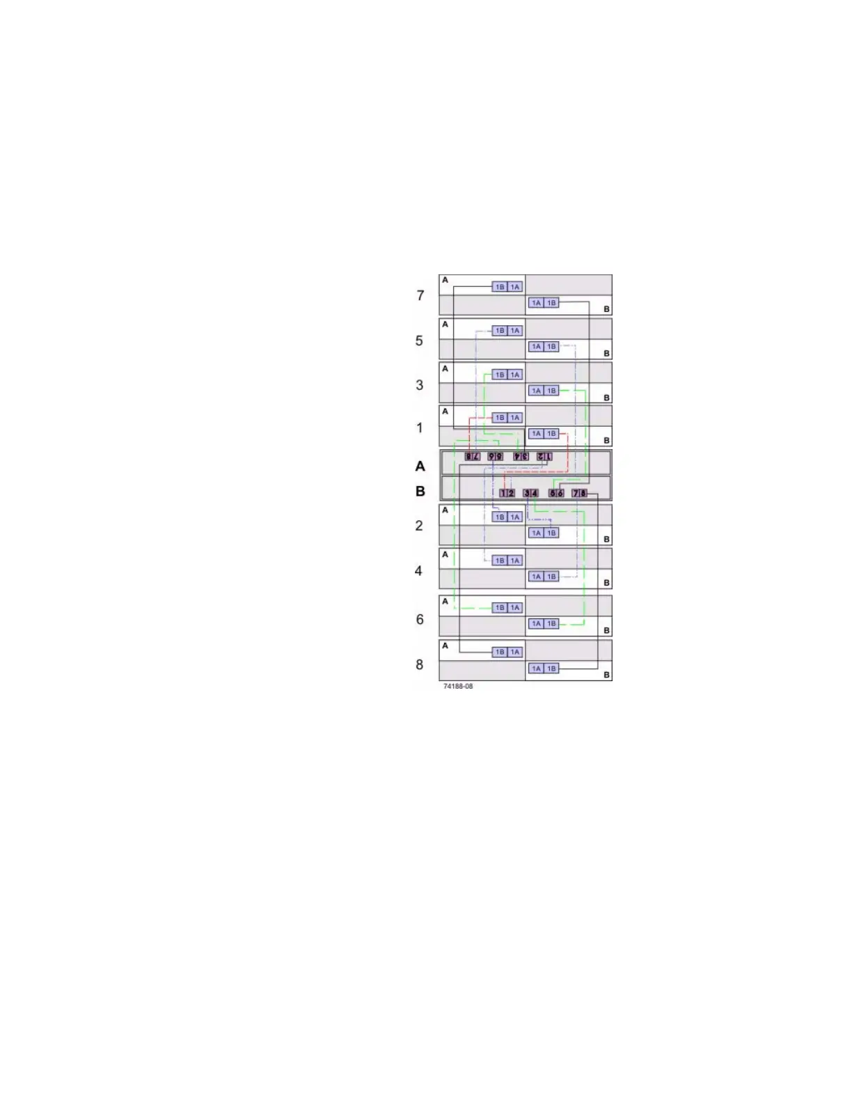
The following figure shows a typical scenario. In this example, each of the eight drive
trays has two connections directly to the controller tray: one from Environmental
Services Module A to controller A and one from ESM B to controller B. Each
redundant path pair on the controller tray connects to one drive tray. The ESM 1B
ports are used for all of the connections.
Figure 6 Cabling for Eight Drive Trays
Note how the controller tray (denoted by A and B in the figure) is conveniently
situated in the middle of the arrangement, which enables you to use cables that are all
the same length. Positioning the controller tray near the middle of the cabinet also
helps prevent the cabinet from becoming top heavy as drive trays are added.
For examples, ranging from simple to complex, see the topics under "Drive
Connection" on page 59.