Chapter 4: Drive Connection 73
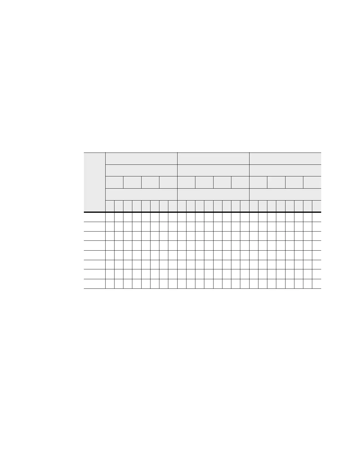
The following table specifies the cabling pattern for a controller tray that is attached
to one to four drive trays. The “Cable” column indicates that two cables are used for
each drive tray. In the rows for cable 1 and cable 2, for example, the “Xs” indicate
that the cables are connected to controller A, channel 1, port 8 and controller B,
channel 5, port 1 respectively. The “Bs” in these rows indicate that the other ends of
cable 1 and cable 2 are connected to port 1B of the left ESM (ESM A) and port 1B of
the right ESM (ESM B) of drive tray 1 respectively. This pattern continues, using
even-numbered ports on controller A and odd-numbered ports on controller B for the
first four drive traydrive trays.
Table 6 One CE7922 Controller Tray or CE7900 Controller Tray and One to Four
Drive Trays
Cable
Controller A Controller B
Channel Number Channel Number Drive Trays
Ch1 Ch2 Ch3 Ch4 Ch5 Ch6 Ch7 Ch8 1 2 3 4
Port Number Port Number ESMs (Left or Right)
8 7 6 5 4 3 2 1 1 2 3 4 5 6 7 8 L R L R L R L R
1X B
2XB
3X B
4XB
5X B
6XB
7X B
8XB