ii. Select Teaming and failover, and select the Override checkbox.
iii. Move vmnic4 to Standby adapters by using the arrow icon.
iv. Select OK.
i. With vSwitch1 selected, from the Actions drop-down menu, select Add Networking and enter the
following details in the window that is displayed:
i. For connection type, select VMkernel Network Adapter, and select Next.
ii. For target device, select the option to add a new standard switch, and select Next.
iii. Select +.
iv.
In the Add Physical Adapters to Switch window, select vmnic1 and vmnic5, and select OK.
vmnic1 and vmnic5 are now listed under Active adapters.
v. Select Next.
vi. Under port properties, change the network label to iSCSI-B, and select Next.
vii.
Under IPv4 settings, provide the IPv4 information, and select Next.
The IP address you enter here is the iSCSI-B IP address that you copied earlier.
viii.
If you are ready to proceed, select Finish.
vSwitch2 is displayed in the list of virtual switches.
j. Select vSwitch2, and select the pencil icon to edit the settings as follows:
i. Under Properties, set MTU to 9000, and select OK.
k. In the graphic that is displayed, select iSCSI-B, and select the pencil icon to edit the settings as
follows:
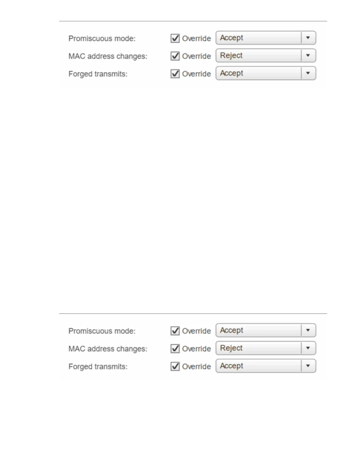
i. Select Security, and make the following selections:
ii. Select Teaming and failover, and select the Override checkbox.
iii. Move vmnic1 to Unused adapters by using the arrow icon.
iv. Select OK.
l. From the Actions drop-down menu, select Add Networking and enter the following details in the