13 DISMANTLING AND ASSEMBLY
OF SPECIAL UNITS
PAGE
13.8R
4.5 iFD-Stators
®
(all sizes)
iFD-Stators
®
1.0
The stators are delivered with a temperature conduit (4570) already built-in.
Stator ( 3005) installation into NEMO
®
pump must be carried out that sensor conduit
(4570) comes on stator suction side.
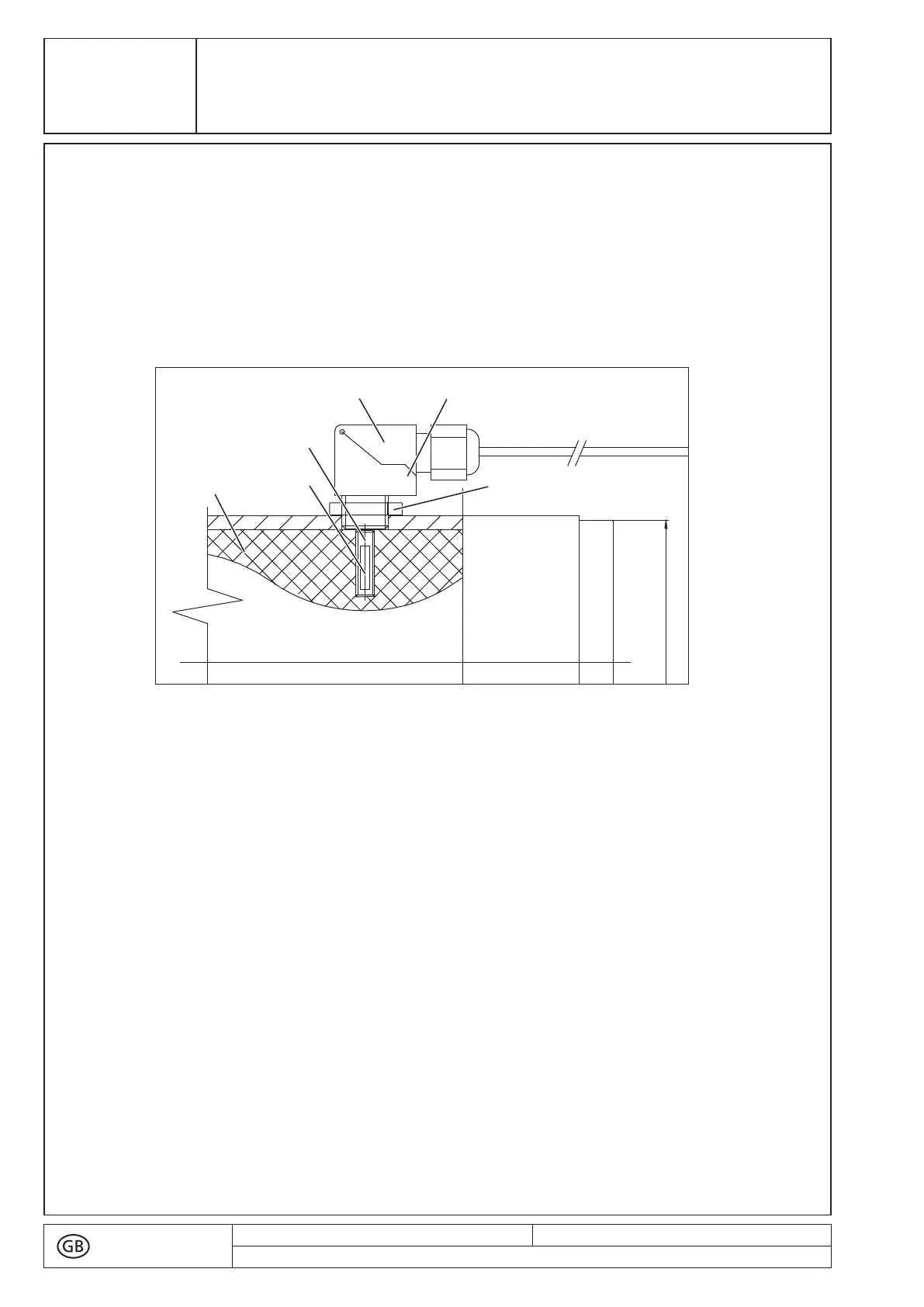
Fig. 4: Installation in iFD-Stators
®
■ Apply some heat transfer paste to the sensor conduit (4570).
■ Mounting snap elbow (4710):
■ Where a snap elbow (4710) is folded down, please unfold by simultaneously
undoing both hooks at (A) with the help of two screw drivers.
■ Screw the snap elbow (4710) into the thread of the iFD stator housing (3001) and
loosen the screwed cable gland. Screw in the snap elbow (4710) only until it
touches the stator elastomer. Turn it back to align it with the housing and fix it in
this position by the nut (4650).
■ Insert the temperature sensor (4180) through the screwed cable gland down to the
bottom into the sensor conduit (4570).
■ Tighten the screwed cable gland while the cable is straight so that the cable is
fixed in the seal rubber.
■ Snap the elbow part (4710) shut with hooks (A) engaged on both sides.
▲ The temperature controller can be integrated into a switch board.
For installation dimensions pl. see Technical Data in section 2.
text no.
R 13105-4/8
issued: 14.10.2019
Revision: 23
copy to:
!
¬D
90
 Loading...