LBP2 User Guide Document No: 50306-001 Rev G 3/12/2020 Page 35
2.5.2 Beam Width Basis
The Beam Width Basis selects which method will be used to draw the Beam Width
aperture in both the 2D and 3D displays. It also affects which clip level method is
employed when computing a beam rotational orientation.
Use the dropdown edit control and select the Beam Width Basis. Choose the
primary spatial display units in the right-hand dropdown control.
The D4σ choice is the preferred Second Moment calculation method.
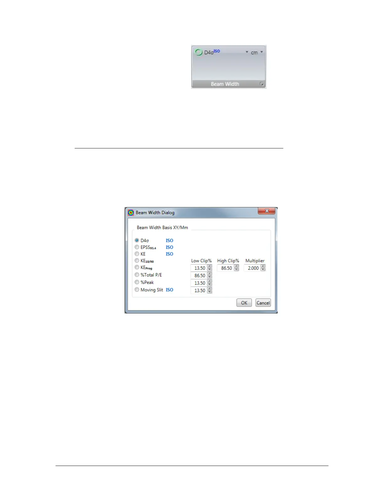
The button in the lower right corner will open an expanded Beam Width Basis
dialog box, shown below. Some of the Beam Width results item choices require
additional input parameters in order for them to be correctly and meaningfully
applied. The required input parameters can be entered here. The factory default
settings are shown below.
Note: A computational description of these Beam Width and Diameter setting
notations is contained in CHAPTER 5.
2.5.2.1 Programmable Knife Edge
KEProg KE Clip%
These are the settings for the user programmable Knife Edge Clip level entries.
Specify a Low and a High % of power clip level and a Multiplier correction
factor. 13.5% and 86.5% with a 2x multiplier is the default setting and
represents the second moment settings for a TEM
00
Gaussian beam.
2.5.2.2 Programmable % of Total Power/Energy
%P/E Clip%
Enter the percent of power/energy contained to set the clip level for
computing the beam widths and diameters using this method. 86.5% is the

 Loading...


