4.8 Sweep Setting and Manipulation
93
WF1973/WF1974
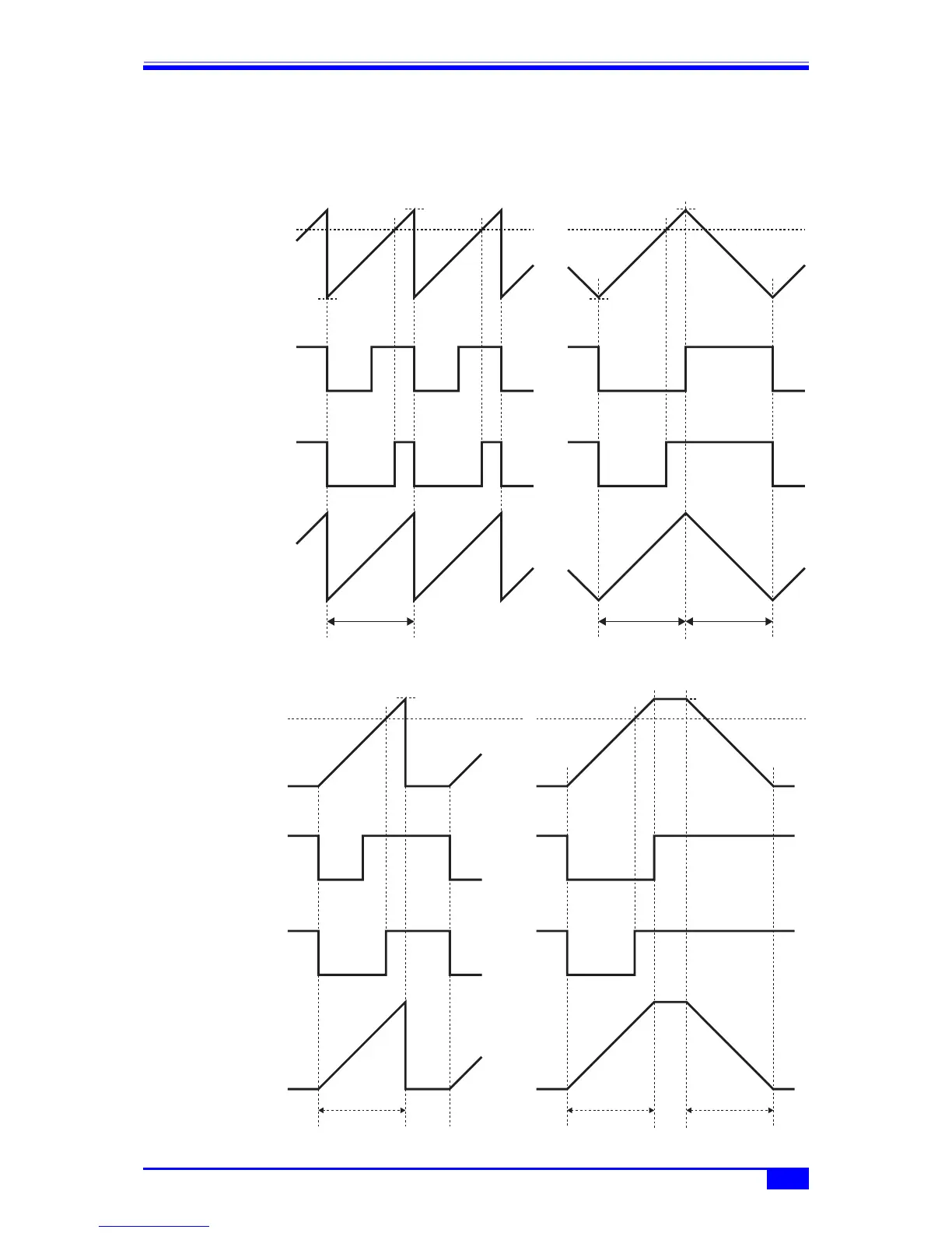
The relationships between the sweep values and the various signals are shown in the
following figure. When stop value < start value, the slope of the sweep X drive output is the
opposite of that in the figure.
Continuous sweep
Single-shot sweep, gated single-shot sweep
Sweep value
Sweep sync
signal SwpSync
(marker disabled)
Sweep sync signal
SwpSync+Mkr
(marker enabled)
Sweep X drive
signal X-Drive
Marker value
Marker value
Start value Start value
Stop value
One way
Stop value
Shuttle
Low from
start value to
marker value
Low from
start value to
marker value
Low from
start value to
marker value
0 V
Sweep time
+3 V
Sweep time Sweep time
Low from start
value to stop
value
Low during
the 1st half
of interval
from start
value to
stop value
Sweep value
Sweep sync
signal SwpSync
(marker disabled)
Sweep sync signal
SwpSync+Mkr
(marker enabled)
Sweep X drive
signal X-Drive
Marker value Marker value
Start value Start value
Stop value
One way
Stop value
Shuttle
Low during
the 1st half
of interval
from start
value to
stop value
0 V
Sweep time
+3 V
0 V
+3 V
Sweep time Sweep time
Low from start
value to stop
value
Low from
start value to
marker value
Low from
start value to
marker value