2
1. OVERVIEW
MULTIFUNCTION GENERATOR
1.2 Operating Principles
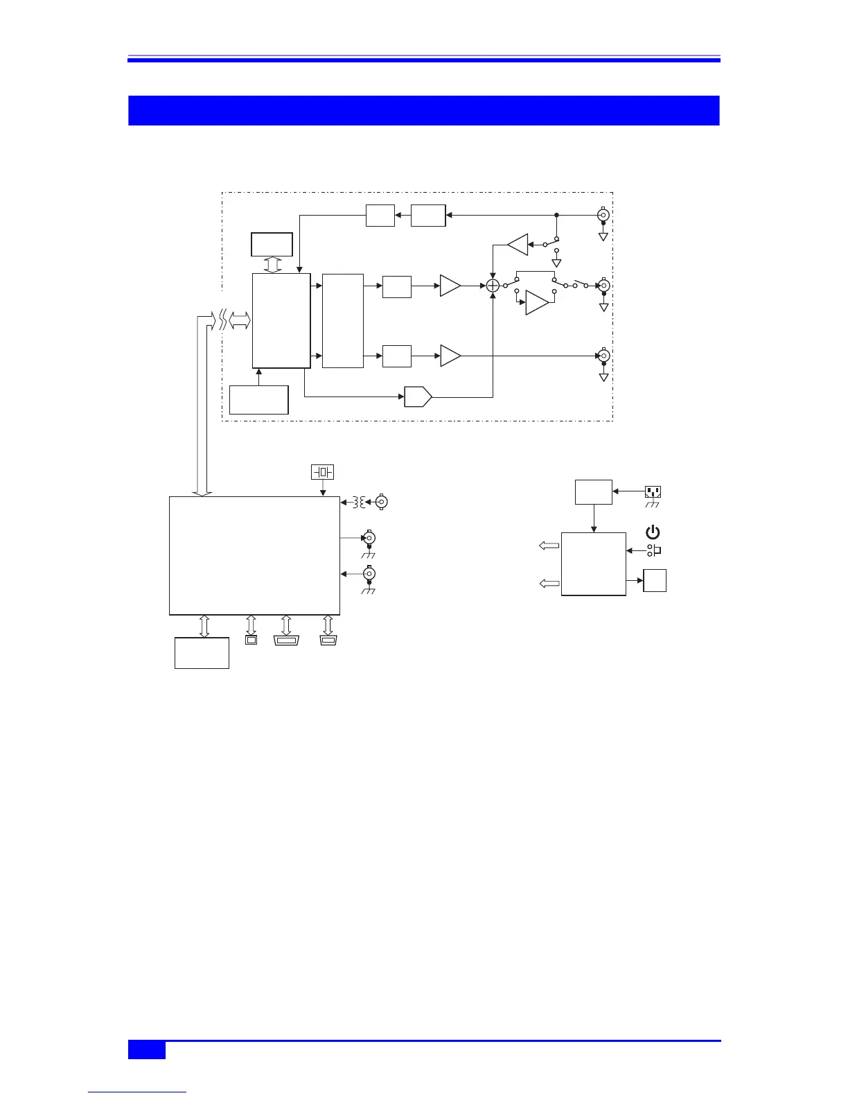
■ WF1973 block diagram
■ Analog block
• The DDS (digital direct synthesizer) uses a 120 MHz clock to generate various types of
oscillation and waveforms. Modulation, sweep, burst, and sequence are also processed
within the DDS.
• The digital waveforms generated by the DDS are controlled to the specified polarity
(normal, inversed) in the amplitude range (−FS/0, ±FS, 0/+FS), and following digital
amplitude adjustment, the signal is input into the digital to analog (D/A) converter.
• The waveform converted into an analog signal by the D/A is then smoothed by the lowpass
filter (LFP), and the amplitude is controlled in 10 dB steps by the programmable gain
amplifier (PGA).
• The external addition signal and DC offset are added to the PGA output. When an output
voltage exceeding ±2V/open is required, output is done via the ×5 amplifier.
• The maximum output voltage of the product is either 20 Vp-p or 4 Vp-p depending on
whether or not the ×5 amplifier is used. Also depending on this, the external addition gain
is either ×10 or ×2.
• After passing through the LPF, the external modulation signal undergoes A/D conversion
and is then input to the DDS.
ANALOG
REF OUT
TRIG IN
10MHz REF IN
for ANALOG
+12V
100V...230V
㨪LINE
MOD/ADD
IN
FCTN
OUT
SYNC/SUB
OUT
A/D LPF
LPF
D/A
DC OFFSET
120MHz
r10Vmax
PGA
0/-10/-20/-30dB
LPF
r1V
2
TTL/r3V
5
r2Vmax
EXTERNAL
MODULATION
EXTERNAL
ADDITION
ISOLATION
DDS
WAV E
MEMORY
16bit
512Kw
16bit-
2CH
D/A
CLOCK
GENERATOR
20MHz
SYSTEM
CONTROLLER
MULTI
I/O
GPIBUSB
FRONT
PA N E L
UNIT
AC/DC
POWER
SUPPLY
FA N
for SYSTEM
CONTROLLER