64
4. BASIC OPERATION
MULTIFUNCTION GENERATOR
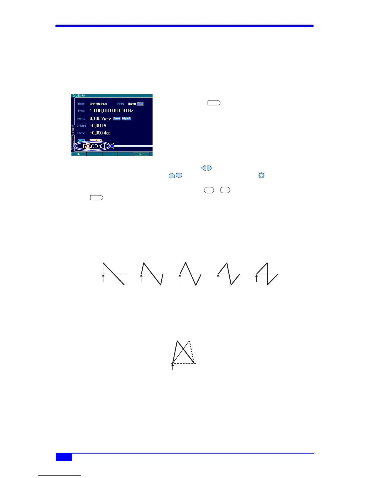
4.4.16 Setting the ramp wave symmetry
The waveform is assumed to be set to [Ramp] (ramp wave). For the waveform setting
method, ) p. 44.
The symmetry setting unit is % only. Setting and display with time is not possible.
a) Symmetry setting method
1. Select the [Symm] field and then press the
ENTER key to open the symmetry
input field.
Even if there are several setting screens,
the [Symm] field is always displayed on
the first page.
2. Select the digit to be changed with the left/right arrow keys, and increment/
decrement the value with the up/down arrow keys or the modify knob. The
change is instantly reflected to the output.
Alternatively, enter a numeric value using the ... numeric keypad. Then press the
ENTER key or the [%] unit key (soft key) to set the input value and reflect it to the
output. If the ENTER key is used, the unit is set to %.
b) Relationship between symmetry and waveform
One waveform cycle changes as follows according to the symmetry setting. A symmetry is
expressed by the amount of the ratios of the first and second rises. Except in the case of 0%
symmetry, the phase zero position is fixed to the 0 amplitude center position.
If it is preferable for the phase zero position to be at the bottom of the waveform, use the
bottom referenced ramp wave of a parameter-variable waveform. ) “1.2.7 Other waveform
group” in the Application Instruction Manual
Symmetry input
field
ENTER
0
9
ENTER
100%80%50%20%0%
Phase
zero position
Phase
zero position
Phase
zero position
Phase
zero position
Phase
zero position
Phase
zero position
Example of 20% and 80% symmetry
for bottom referenced ramp wave