18
3. PANELS AND I/O TERMINALS
MULTIFUNCTION GENERATOR
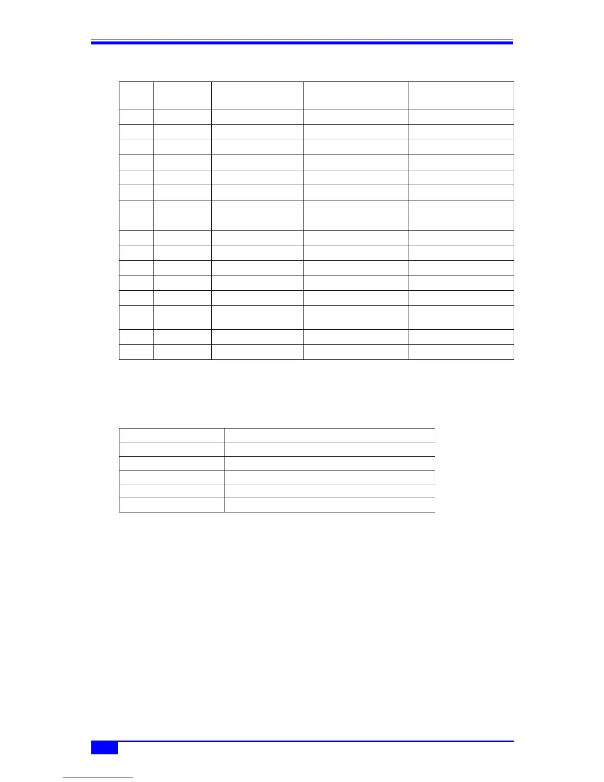
Table 3-2. Multi-I/O Connector Function Allocation
Note: +5 V is output for testing purposes during production to pin No. 9. This pin is not designed for
use by users. Leave this pin unconnected, as its use may cause the operation of the equipment to
become unstable.
■ I/O characteristics
The connection cable is an option. Contact NF Corporation or an NF distributor for details.
Pin No. I/O
Sweep Oscillation
Mode
Sequence Oscillation
Mode
Option Cable Color and
Marking
1 Output Not used Step sync code D0 (LSB)
Light brown Black ■
2 Output Not used Step sync code D1
Light brown Red ■
3 Output Not used Step sync code D2
Yellow Black ■
4 Output Not used Step sync code D3 (MSB)
Yellow Red ■
5 Output Not used Not used
Bright green Black ■
6 GND – –
Bright green Red ■
7 GND – –
Gray Black ■
8 GND – –
Gray Red ■
9 Reserved Leave unconnected Leave unconnected
White Black ■
10 GND – –
White Red ■
11 Input Not used Sequence event branch
Light brown Black ■■
12 Input Sweep hold/resume Sequence hold/resume
Light brown Red ■■
13 Input Sweep stop Sequence stop
Yellow Black ■■
14 Input Sweep start Sequence start or state
branch
Yellow Red ■■
15 Input Not used Not used
Bright green Black ■■
Shell – – –
Bright green Red ■■
Input voltage TTL level (low: 0.8 V or lower; high: 2.6 V or higher)
Maximum allowed input −0.5 V to +5.5 V
Input impedance 10 kΩ, pull up to +5 V
Output voltage TTL level (low: 0.4 V or lower; high: 2.7 V or higher)
Signal GND Same potential as housing
Connector Mini D-sub 15-pin