Control
FIGHTER 1110
For Home Owners
8
FIGHTER 1110 has a two-line LCD display. The heat
pump can be set via this display and its associated
buttons.
Channel selection
The Channel button lets you browse through
the following display modes to find the informa-
tion you require.
Values within brackets are also described within
brackets.
If a value is programmable, this is denoted by a [P] (
Programmable) in front of the value.
If the next value cannot be changed, you can access
the next menu by pressing Channel.
Setting
The first step when changing a value is to press
the Increase button once. A cursor (line) then
appears under the value. Now you can either
increase or reduce the value with the Increase
or Reduce buttons.
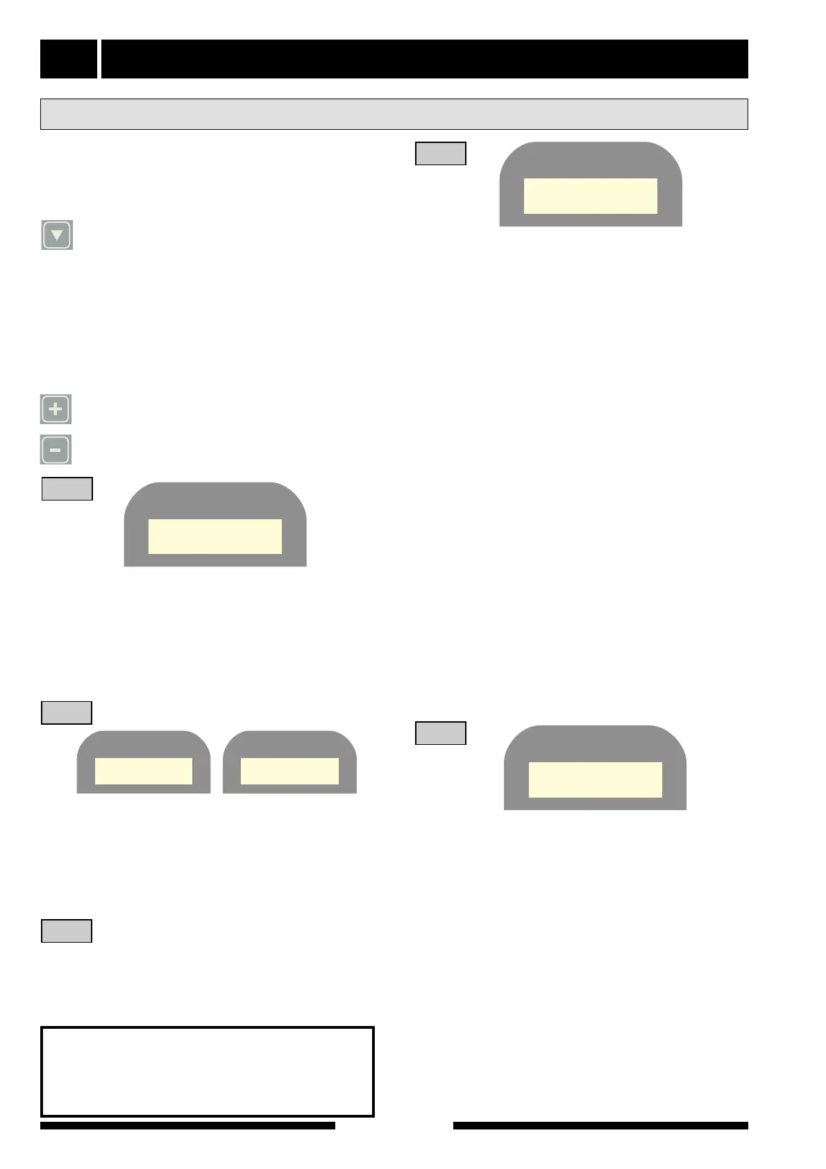
Available information and on-display settings
In normal mode, the above information appears on
the LCD-display of the heat pump.
WW-out
Current flow temperature
(Calculated flow temperature.)
Hot water
Indication of the hot water temperature.
1
Outdoor
Current outdoor temperature.
Room
Current room temperature. Only shown if a room
sensor is connected
[P] (The set Set point value on the room sensor.)
Setting range: 5 - 30 °C.
2
Boiler *
Current boiler water temperature.
(Start temperature for shunting-in from boiler.)
* Only shown if a boiler sensor is connected.
2b
Brine In
Temperature of the brine in.
Brine Out
Temperature of the brine out.
[P] (Minimum permitted temperature for the brine
fluid return from the heat pump).
This setting should only be changed by a special-
ist. It is used for minimum limiting with alarm, for
example as an anti-freezing function in ground-
water systems or exhaust air systems.
A suitable setting with an intermediate heat
exchanger would be 0 °C. When the lowest value
(-12) is set, minimum limiting and the alarm are
disabled.
Setting range: -12 – +10 °C.
WW-in
Current temperature of incoming heating medi-
um.
[P] (Max permitted return temperature.)
Setting range: 40 – 55°C and A.
Setting WW-in
Maximum permitted return temperature for com-
pressor operation. To change, press the Increase
button once. A cursor will appear under the figure
for
WW-in. Press the Increase or Reduce button to
obtain the required value. If the value A is selected,
(automatic indirect control of the return tempera-
ture) the operating pressure switch will indirectly
limit the return temperature. Press the Channel
button to continue.
HW start
The current temperature at the bottom part of the
water heater’s outer shell.
[P] (Chosen start level for hot water production.)
Setting range: 30 - 49 °C.
Setting HW start
Press the Channel button. A cursor then appears
within the brackets for HW start. Press the
Increase or Reduce button to select the start tem-
perature for the hot water heating.
Press the Channel button to continue.
3
4
NOTE!
Enter the selected values on page 2 in
this Installation instruction. The details
are important for service work.
WW-out 47(52) °C
Hot water 48 °C
Outdoor -14 °C
Room 20.5(20)°C
Outdoor -14 °C
Boiler 70(55)°C
WW-in 37(53) °C
HW start 49(44) °C
Brine In +3 °C
Brine Out 0(-12) °C