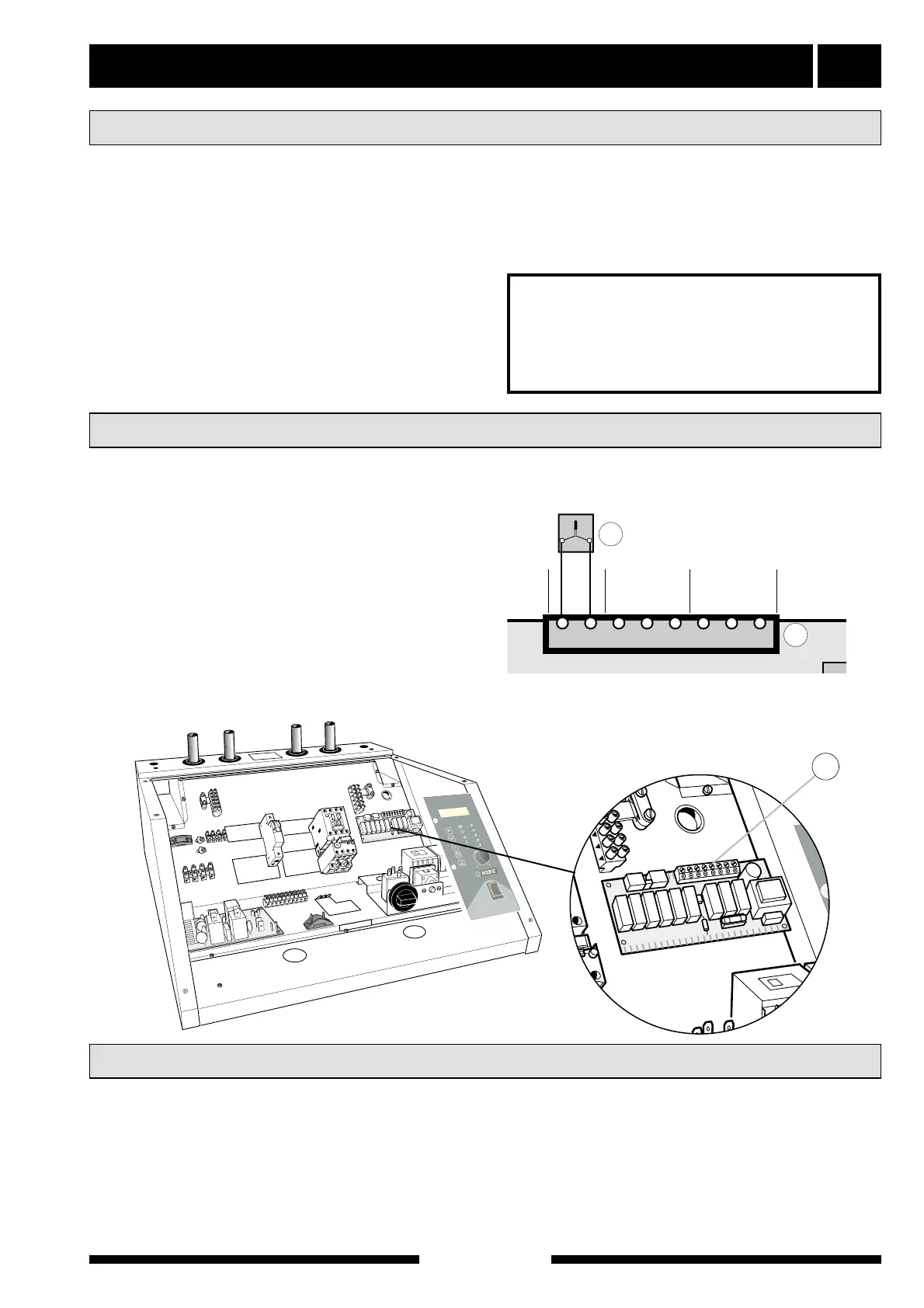
■ The outside sensor (15) must be installed in a
shaded location on a wall facing north or north-
west, where it will not be affected by any morning
sun. The sensor is connected by two wires to ter-
minals 7 and 8 of terminal block 30 on the relay
card (29). The minimum cable cross section is 0.4
mm
2
up to 50 metres. Suitable cable types are
EKKX or LiYY.
■ If the outside temperature sensor cable runs close
to power cables, screened cable should be used. If
a conduit is used it must be sealed to prevent con-
densation in the sensor capsule.
■ The outdoor sensor should be connected, e.g. to
the heat pump with fixed condensing.
Electrical connection 21
For the Installer
FIGHTER 1110
■ A heat pump must not be connected without the
permission of the electricity supplier and must be
connected under the supervision of a qualified
electrician.
■ If an automatic fuse unit is used this should have a
motor characteristic D (compressor operation). For
MCB size see Technical Specifications.
■ The FIGHTER 1110 does not include an isolator
switch on the incoming electrical supply. Therefore
the installation must be preceded by a circuit-
breaker.
■ If an insulation test is to be carried out in the build-
ing, disconnect the heat pump.
■ Connect the heat pump to 400 V 3-phase, neutral +
ground via a distribution board with fuses. Does not
apply to FIGHTER 1110-4 kW without electrical
supplement, where 230V 1-phase + ground is suffi-
cient.
■ Connect an external, potential free make contact to
terminal (30) pos 1 and 2 to disconnect the entire
electrical output.
■ Connect an external, potential free make contact to
terminals 1 and 3 on terminal block (30) to discon-
nect the entire electrical output, but with the possi-
bility to use Extra hot water during the period with-
out output.
■ Connect the load monitor EBV 200 (accessories) to
terminal (30) pos 1 and 2 to disconnect the electri-
cal output in steps.
■ Disconnection of the entire electrical power is
achieved by connecting an external potential-free
make (NO) contact to terminal (30) pos 1. and 2
together with pos 3 (pos 2 and 3 are connected
together).
Connection
Connecting the outside sensor
External control of the immersion heater
NOTE!
A 1-phase connection without
electrical supplement requires pos L1
and L3 to be strapped on terminal (9).