Electrical connection
FIGHTER 1110
For the Installer
22
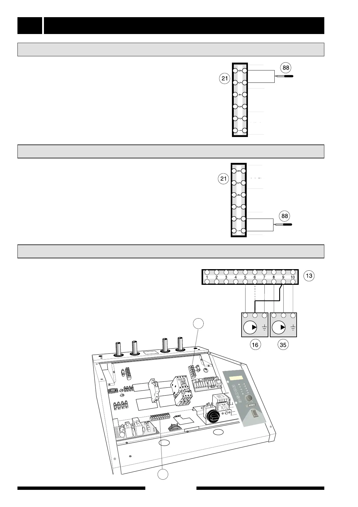
Existing sensors are disconnected from terminal (21),
positions 1 and 2. The supplied sensor is connected
instead via a two-wire cable to this position. The sen-
sor is placed in the submerged tube on the electric
boiler/accumulator tank.
See docking options 5 – 6.
For fixed condensing the electrical connection for the
heat medium pump (16) is moved from position 6 to
position 9 on terminal (13) and is then connected in
parallel to the heat transfer fluid pump (35). This refers
to docking options 5 and 6, see the Docking section.
Connection of heat medium pump for fixed condensing
Connecting the supplied temperature sensor with fixed condensing
The supplied sensor is connected using a two-wire
cable to terminal (21) positions 5 and 6. The sensor is
placed in a submerged tube on the accumulator tank,
e.g. VPA.
See docking options 1 – 4.
Connecting the supplied temperature sensor with floating condensing
13
21
The figure shows FIGHTER 1110, 5 — 15 with
electrical supplement ETS 11.