EasyManuals Logo
Home>Nice>Garage Door Opener>Spido

Nice Spido Instructions And Warnings For Installation And Use

Nice Spido
36 pages
To Next Page IconTo Next Page
To Previous Page IconTo Previous Page
Page #10 background imageLoading...
Page #10 background image
10 – ENGLISH
ELECTRICAL CONNECTIONS
4
4 ELECTRICAL CONNECTIONS
4.1 PRELIMINARY CHECKS
f
All electrical connections must be made with the
system disconnected from the mains electricity and
with the back-up battery (if present) disconnected.
a
The connection operations must only be carried out
by qualied personnel.
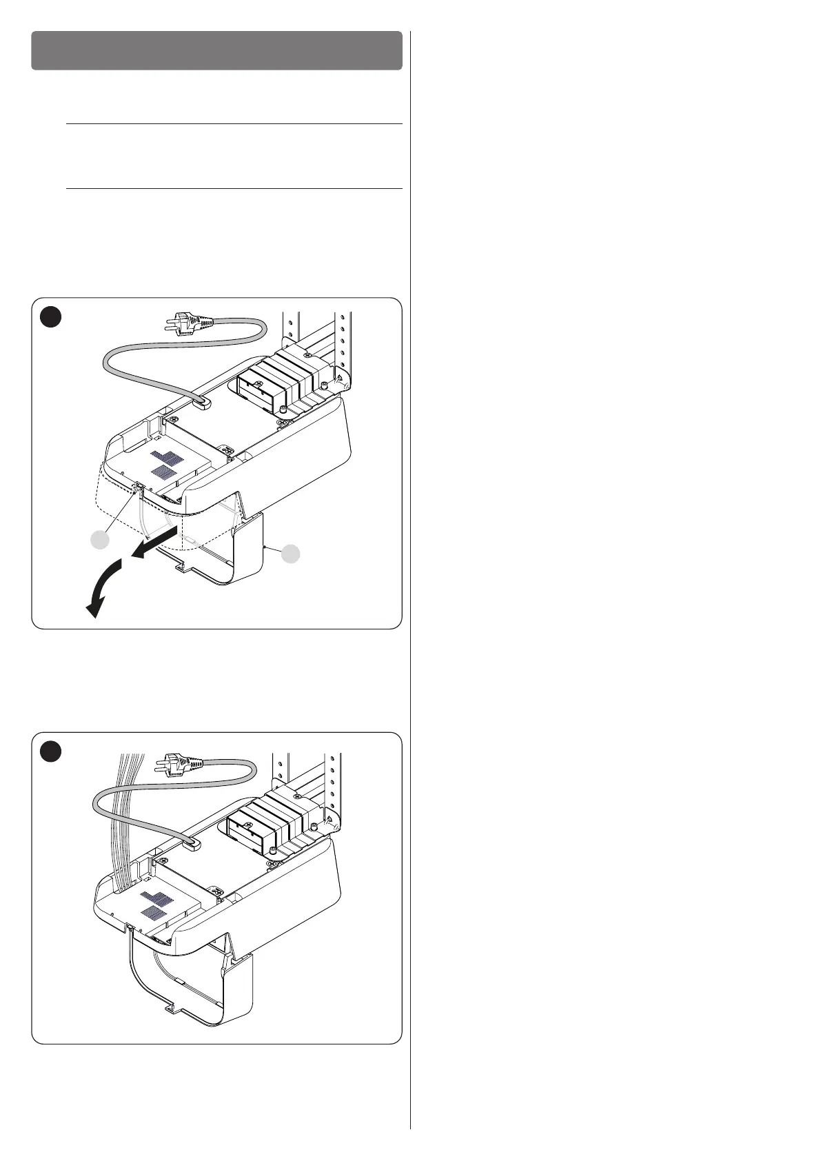
To make the electrical connections:
1. loosen the screw (A)
2. pull the cover (B) slightly outwards and turn it downwards
(“Figure 25“)
A
B
25
3. insert all the connecting cables into the various devices,
leaving them 20–30 cm longer than necessary. Refer to “
Table 2” for the type of cables and to “Figure 27for
the connections.
4. use a cable tie to group all the cables entering the gearmotor
(“Figure 26“)
26

Table of Contents

Other manuals for Nice Spido

Questions and Answers:

Question and Answer IconNeed help?

Do you have a question about the Nice Spido and is the answer not in the manual?

Nice Spido Specifications

SP6000

Power IconPower
power input230 Vac ±10%, 50 / 60Hz
flashing light output voltage24 Vac
flashing light output power25 W
Operating Environment IconOperating Environment
operating temperature-20 °C - 70 °C
maximum duration of a manoeuvre60 seconds
courtesy light time60 seconds
Service Supply IconService Supply
service supply output voltage24 Vac
service supply maximum current200 mA
pause timeProgrammable from 5 to 250 seconds

SP6000/V1

Power IconPower
power input120 Vac ±10%, 50 / 60Hz

Related product manuals