ENGLISH – 5
3.5 PRE-INSTALLATION WORKS
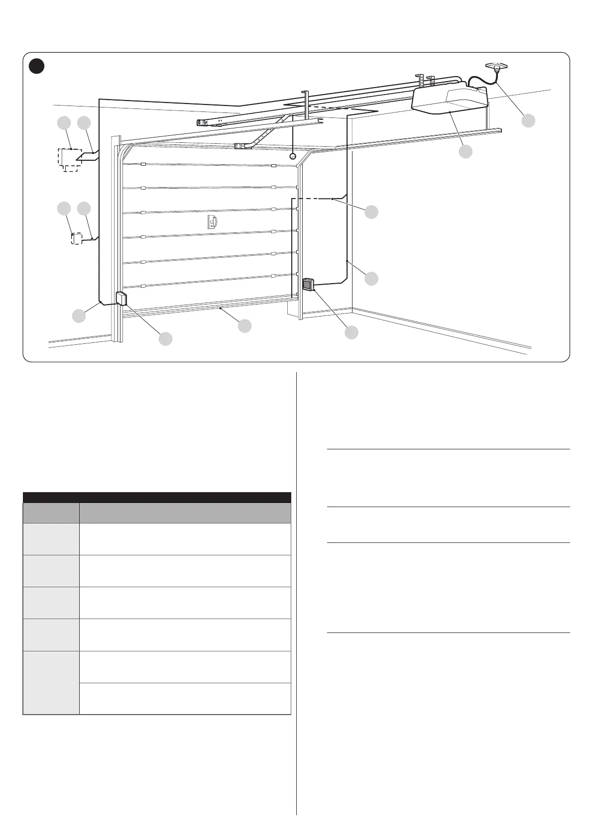
The gure shows an example of an automation system, constructed using Nice components.
A
1
2
B
3
C
4D
5E
B
3
5
A Gearmotor
B Photocells
C Main edge
D Key selector
E Warning light with incorporated antenna
The above-mentioned components are positioned according to a
typical standard layout. Using the layout shown in “Figure 5” for
reference, dene the approximate position in which each compo-
nent of the system will be installed.
Table 2
TECHNICAL SPECIFICATIONS OF ELECTRICAL CABLES
Identication
no.
Cable characteristics
1
GEARMOTOR POWER SUPPLY cable
1 cable 3 x 1.5 mm
2
Maximum length 30 m [note 1]
2
MAIN EDGE cable
1 cable 2 x 0.5 mm
2
Maximum length 20 m
3
PHOTOCELL cable
1 cable 4 x 0.5 mm
2
Maximum length 30 m
4
KEY SELECTOR cable
2 cables 2 x 0.5 mm
2
[note 2]
Maximum length 50 m
5
WARNING LIGHT cable
1 cable 2 x 0.5 mm
2
Maximum length 20 m
ANTENNA cable
1 x RG58-type shielded cable
Maximum length 10 m; recommended < 5 m
Note 1 If the power supply cable is longer than 30 m, a cable with
larger cross-sectional area (3 x 2.5 mm
2
) must be used
and a safety earthing system must be installed near the
automation.
Note 2 These two cables can be replaced by a single 4 x 0.5 mm
2
cable.
a
Before proceeding with the installation, prepare the
required electrical cables by referring to “Figure 5”
and to that stated in the “TECHNICAL SPECIFICA-
TIONS” chapter (page 31).
a
The cables used must be suited to the type of envi-
ronment of the installation site.
a
When laying the pipes for routing the electrical ca-
bles, take into account that any water deposits in
the junction boxes may cause the connection pipes
to form condensate inside the control unit, thus
damaging the electronic circuits.
“Figure 6” shows typical installations for a protruding and non-pro-
truding overhead door.
m
For installation on protruding and non-protruding
doors, accessory SPA5 is required.

 Loading...


