ENGLISH – 29
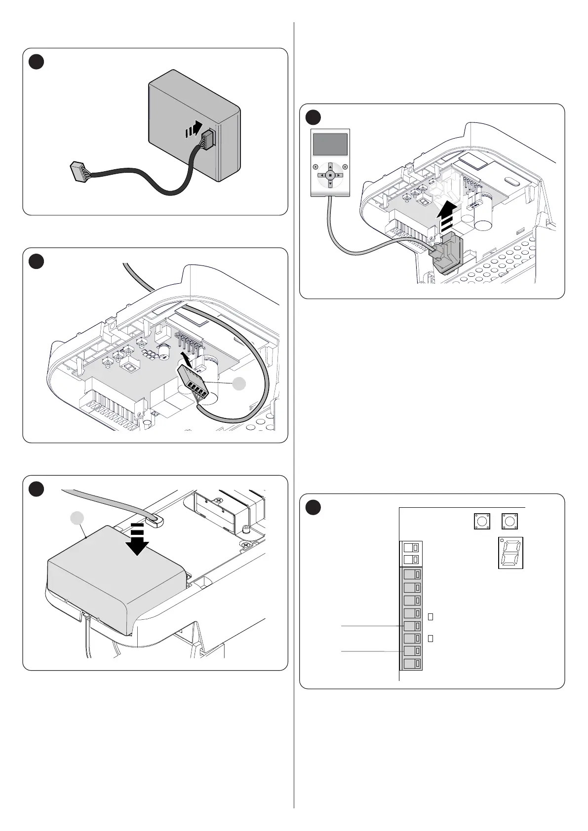
3. connect the appropriate cable to the back-up battery con-
nector (“Figure 57“)
57
4. insert the relative connector (C) on the control unit (“Figure
58“)
C
58
5. insert the back-up battery (D) into its housing inside the mo-
tor body (“Figure 59“).
D
59
9.3 CONNECTING THE OVIEW PROGRAMMER
The control unit has a BusT4 connector to which the “Oview”
programmer can be connected, through the IBT4N interface. The
programmer allows for fully and rapidly managing the installation,
maintenance and diagnosis of the entire automation.
To access the connector, proceed as shown in the gure and con-
nect the connector to its relevant slot.
60
The Oview can be connected to multiple control units simultane-
ously (up to 16 without any particular precautions) and can be left
connected to the control unit during the automation’s normal oper-
ation. In this case, it can be used to send commands directly to the
control unit using the specic “user” menu.
It is also possible to update the rmware. If the control unit has a
radio receiver belonging to the OXI family, the “Oview” can be used
to access the transmitter parameters memorised in the receiver.
For more detailed information, consult the respective instruction
manual and the “Opera system book” manual.
9.4 CONNECTING OTHER DEVICES
If the user needs to power external devices, such as a proximity
reader for transponder cards or the light of the key selector switch,
power can be tapped as shown in the gure.
The power supply voltage is 24V c -30% ÷ +50% with a maxi-
mum available current of 100mA.
1
2
345
6
78
24 V (+)
0 (-)
61

 Loading...


