4 – ENGLISH
INSTALLATION
3
3 INSTALLATION
3.1 PRE-INSTALLATION CHECKS
a
The installation must be carried out by qualied
personnel in compliance with the current legisla-
tion, standards and regulations, and with the in-
structions provided in this manual.
Before proceeding with the product’s installation, it is necessary to:
– check the integrity of the supply
– check that all the materials are in good working order and suited
to the intended use
– make sure that the structure of the door is suitable for being
automated
– make sure that the characteristics of the door fall within the op-
erating limits specied in the “Product usage limits” paragraph
(page 4)
– verify that there are no points of greater friction during the open-
ing and closing movements along the entire door path
– verify that the area where the gearmotor is installed allows for
unlocking the latter and manoeuvring easily and safely
– verify that the mounting positions of the various devices are pro-
tected against impacts and that the mounting surfaces are suf-
ciently sturdy
– prevent any parts of the automation from being immersed in wa-
ter or other liquids
– keep the product away from heat sources and open ames and
acid, saline or potentially explosive atmospheres; these may
damage the product and cause malfunctions or dangerous sit-
uations
– connect the control unit to an electricity supply line equipped
with a safety earthing system
– include a device on the electric power line ensuring complete
disconnection of the automation from the grid. The disconnec-
tion device must have contacts with a sufcient gap to ensure
complete disconnection, under the Category III overvoltage con-
ditions, in accordance with the installation instructions. Should it
be necessary, this device guarantees fast and safe disconnection
from the power supply; it must therefore be positioned in view of
the automation. If placed in a non-visible location, it must have a
system that blocks any accidental on unauthorised reconnection
of the power supply, in order to prevent dangerous situations.
The disconnection device is not supplied with the product.
3.2 PRODUCT USAGE LIMITS
The data relative to the product’s performances is included in the
“TECHNICAL SPECIFICATIONS” chapter (page 31) and is the
only data that allows for properly assessing whether the product is
suitable for its intended use.
Check the application limits of SPIDO and of the accessories to
be installed, assessing whether their characteristics are capable
of meeting the requirements of the environment and the limitations
specied below:
– the door dimensions must be below 10,5 m
2
– the weight of the door must not exceed 110 kg
– the wall-mounting bracket must be sufciently long.
Table 1
SPIDO - LIMITATIONS OF USE IN RELATION TO THE TYPE OF DOOR
Type of door Operating limits (m)
height width
Sectional 2,6 3,7
Non-protruding overhead door
(with accessory SPA5)
2,4 3,5
Protruding overhead door (with
accessory SPA5)
3 3,5
Overhead with springs (without
accessory SPA5)
3 3,5
The measurements shown in “Table 1” are purely indicative
and are only needed for making a rough estimate. The ac-
tual suitability of SPIDO for automating a specic door depends
on the degree of leaf balancing, guide friction and other aspects,
including occasional events such as wind pressure or the presence
of frost, which could obstruct the leaf’s movement.
To determine the actual conditions, the force required to move the
leaf throughout its path must be measured, to ensure that this val-
ue does not exceed the “rated torque” specied in the “TECHNI-
CAL SPECIFICATIONS” chapter (page 31).
a
The control unit is equipped with a manoeuvre lim-
iting device that prevents possible overheating; it is
based on the motor load and duration of the cycles,
and intervenes when the maximum limit is exceed-
ed.
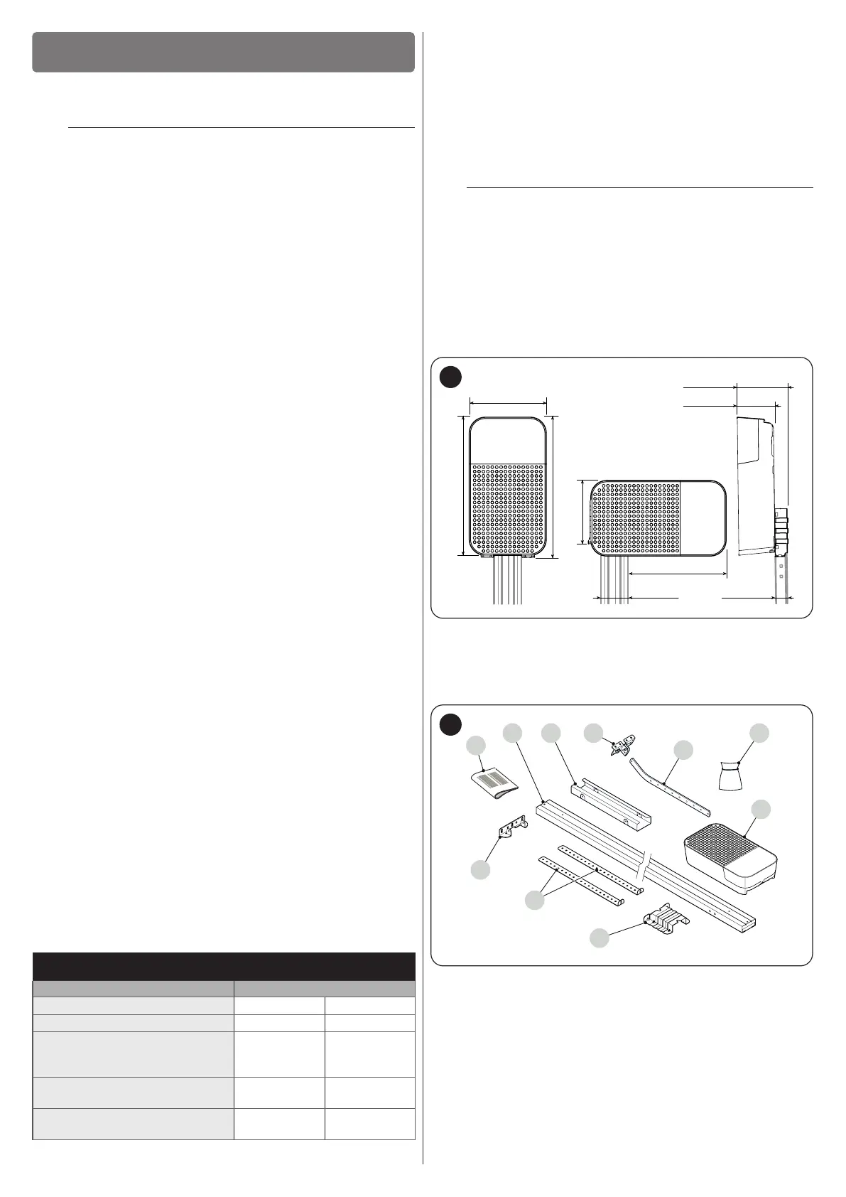
3.3 PRODUCT IDENTIFICATION AND OVERALL
DIMENSIONS
The overall dimensions of the product are shown in “Figure 3”.
161 mm
90 mm
70 mm 30 mm
192 mm
250 mm
350 mm
3
3.4 RECEIPT OF THE PRODUCT
All the components contained in the kit are illustrated and listed
below.
H
I
A
C
G
4
A Gearmotor
B Metal hardware (screws, washers, etc.)
C Drawbar
D Door mounting bracket
E Joining element for guide (in case of a 2-piece guide)
F Assembled / pre-assembled guide
G Quick guide
H Wall mounting bracket
I Ceiling mounting bracket
J Motor mounting bracket

 Loading...


