ENGLISH – 25
8.2 SIGNALS ON THE CONTROL UNIT
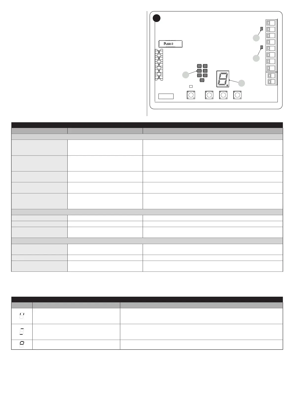
The control unit has a series of LEDs, each of which can emit spe-
cial signals both during regular operation and when an anomaly
occurs.
A OK LED
B STOP LED
C Display
D Courtesy light
1
2
345
6
78
LS - LED STOP
LK -
LED OK
C
D
A
B
DISPLAY
51
Table 17
CONTROL UNIT STATUS VISUALISATION LED
Status Meaning Possible solution
OK LED
OFF Anomaly
Check for the presence of power; check that the fuses are not blown;
if necessary, identify the cause of the fault then replace them with fuses
having the same specications.
On Serious anomaly
There is a serious anomaly; try switching off the control unit for a few
seconds; if the condition persists, it means that there is a fault and the
electronic circuit board must be replaced.
1 green ash per second All OK Normal control unit operation.
2 quick green ashes The status of the inputs has changed
This is normal when there is a change in one of the inputs: SbS, STOP,
intervention of photocells or the radio transmitter is used.
A series of ashes
separated by a 1-second
pause
Various Same signal on the warning light or courtesy light: see “Table 19”.
STOP LED
On All OK Normal operation of the STOP input.
OFF Intervention of the STOP input Check the devices connected to the STOP input.
Warning light
The installation procedure was not
carried out.
Refer to the chapter “Programming the door opening and closing
positions" (page 12).
Courtesy light
On All OK
Manoeuvre being executed or courtesy light timer in downcounting
mode.
OFF All OK Control unit awaiting commands.
Warning light
The “Force search” procedure was
not carried out
See “Automatic force search" (page 14).
Besides the symbols present in the programming menu, the following symbols can appear on the display to signal the status of the au-
tomation or of the current procedures.
Table 18
OPERATION SIGNALS ON THE DISPLAY
Symbol Function Description
Control unit in stand-by
Flashing: devices or positions not acquired (or error). See “Programming the door
opening and closing positions".
Steady: control unit awaiting commands.
Automation in realignment mode
The control unit needs to be realigned because the current position memorised
is not valid. All the manoeuvres will be forced on closing to reach the maximum
closing position.
Opening position programming The control unit waits for the user to conrm the opening position.

 Loading...


