12 – ENGLISH
ELECTRICAL CONNECTIONS
Terminals Description
PHOTOTEST
This output is programmable (refer to the “Setting the PHOTOTEST operation” chapter on page 20) to
connect one of the following devices: PHOTOTEST (Default), Warning light, “Door open indicator” output,
Suction cup [Note 1], Electric latch [Note 1], Electric lock [Note 1], Courtesy light, Radio channel no. 1-4
STOP
Input for the devices that block or, if necessary, stop the manoeuvre under way. With suitable arrangements,
“Normally Closed” or “Normally Open” contacts, or xed resistor or optical devices can be connected to the
input.
For further information on the STOP function, refer to the “STOP input” paragraph (page 27).
SbS
Input for devices that control the movement in Step-by-Step mode; it is possible to connect “Normally Open”
contacts.
PHOTO Input for safety devices: it is possible to connect "Normally Closed" contacts to this input.
AERIAL
Antenna connection input for radio receiver; the antenna is incorporated in the warning light; alternatively, an
external antenna can be used.
Note 1 Only devices containing the electromagnet only can be connected.
FINAL CHECKS AND START-UP
5
5 FINAL CHECKS AND START-UP
5.1 POWER SUPPLY CONNECTION
To connect the gearmotor to the mains electricity, simply insert its
plug into a power socket; if necessary, use a common adapter if
the plug version is not compatible with the relevant socket.
a
Never cut or remove the cable supplied.
a
If a power socket is not already available, the device
must be connected to the power supply by qualied
and expert personnel possessing the necessary re-
quirements and in full conformity to the applicable
laws, standards and regulations.
a
The power supply line must be protected against
short-circuits and ground leakage; a device must
be provided to enable disconnection of the power
supply during the installation and maintenance of
the gearmotor (the plug and socket can be used for
this purpose).
As soon as the product is powered, a few simple checks should
be carried out:
1. check that the OK LED starts ashing at regular intervals of
about 1 ash per second.
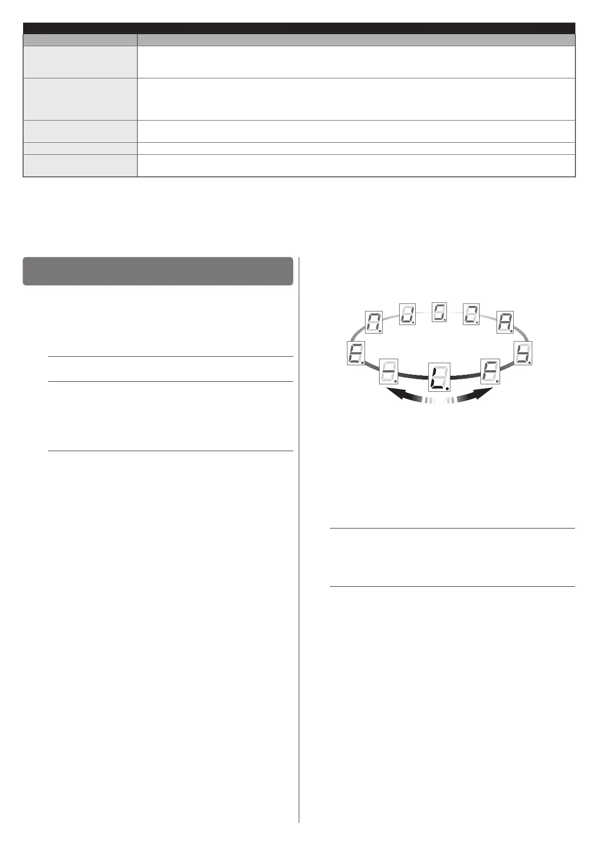
2. wait for the start signal, shown on the display with the sym-
bol “8” ashing rapidly and intermittently for 3 seconds.
3. check that the warning light connected to the FLASH output
is off.
If the above conditions are not satised, immediately switch off the
power supply to the control unit and carefully check the electrical
connections.
Further useful information on fault search and diagnosis is included
in the “Troubleshooting” paragraph (page 24).
5.2 PROGRAMMING THE DOOR OPENING AND
CLOSING POSITIONS
Function found in the INSTALLATION menu.
In order to be able to move the automation correctly, the control
unit must identify whether there are any photocells, the type of
safety devices connected to the STOP input and subsequently
memorise the stop positions.
Preliminary checks:
– check that the belt or chain in the guide is correctly taut
– check the automation’s balancing (the door unlocked by the mo-
tor carriage must remain stationary in any opening position)
– check that the motor carriage is locked.
a
If, during the ensuing procedure, the door must be
moved in the opposite direction, it is necessary to
perform the procedure described in the “Inverting
the direction of motor rotation” chapter (page 14).
a
If, during the programming of the positions, the pro-
cedure is interrupted through a STOP command or
by the intervention of the PHOTO, the movement
will be stopped and the cause of the stoppage sig-
nalled (see “Table 19”). After verifying the cause, the
procedure can be resumed from the point where it
was stopped by pressing the
f
or
h
button again.

 Loading...


