Installation
4.3 Inputs
CAUTION
The control inputs are powered by the soft starter. Do not apply external voltage to
the control input terminals.
NOTE
Cables to the control inputs must be segregated from mains voltage and motor
cabling.
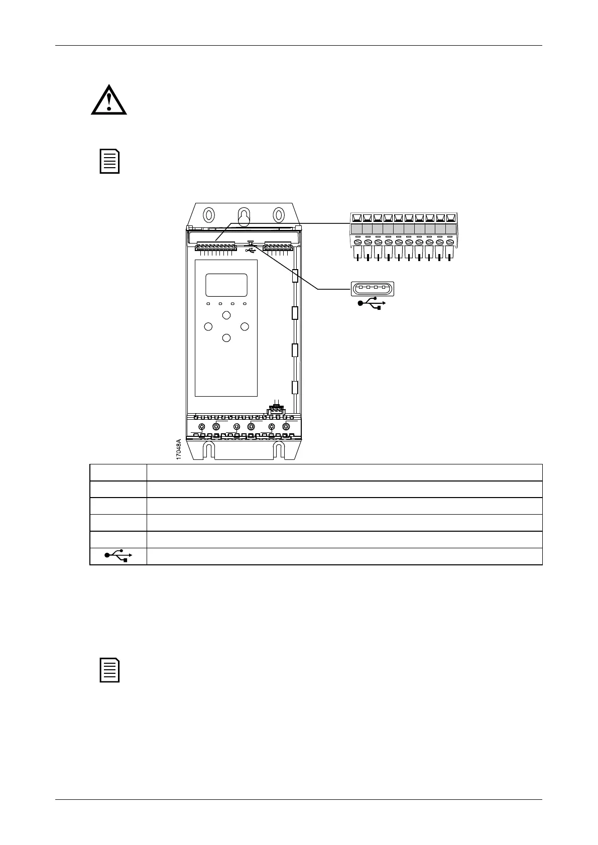
Input terminals
B4 B5 10 11 12 13 14 15 21 22
2/T1 4/T2 6/T3
1/L1 3/L2 5/L3
B4 B5 10 11 12 13 14 15 21 22 33 34 41 42 44 53 54
A3 A1 A2
13, 14 Programmable input A (default = Input Trip (N/O))
Programmable input B (default = Input Trip (N/O))
Motor Thermistor
Motor thermistors can be connected directly to the soft starter. The soft starter will trip when
the resistance of the thermistor circuit exceeds approximately 3.6 kΩ or falls below 20 Ω.
The thermistors must be wired in series. The thermistor circuit should be run in screened
cable and must be electrically isolated from earth and all other power and control circuits.
NOTE
The thermistor input is disabled by default, but activates automatically when a
thermistor is detected. If thermistors have previously been connected to the soft
starter but are no longer required, use the Thermistor Reset function to disable the
thermistor. Thermistor Reset is accessed via the Setup Tools.
19

 Loading...


