www.nitronic.ch - 43 -
Nitronic AG
Mattenstrasse 11
CH – 2555 Bruegg Tel. +41 32 373 7070
Switzerland Fax +41 32 373 70
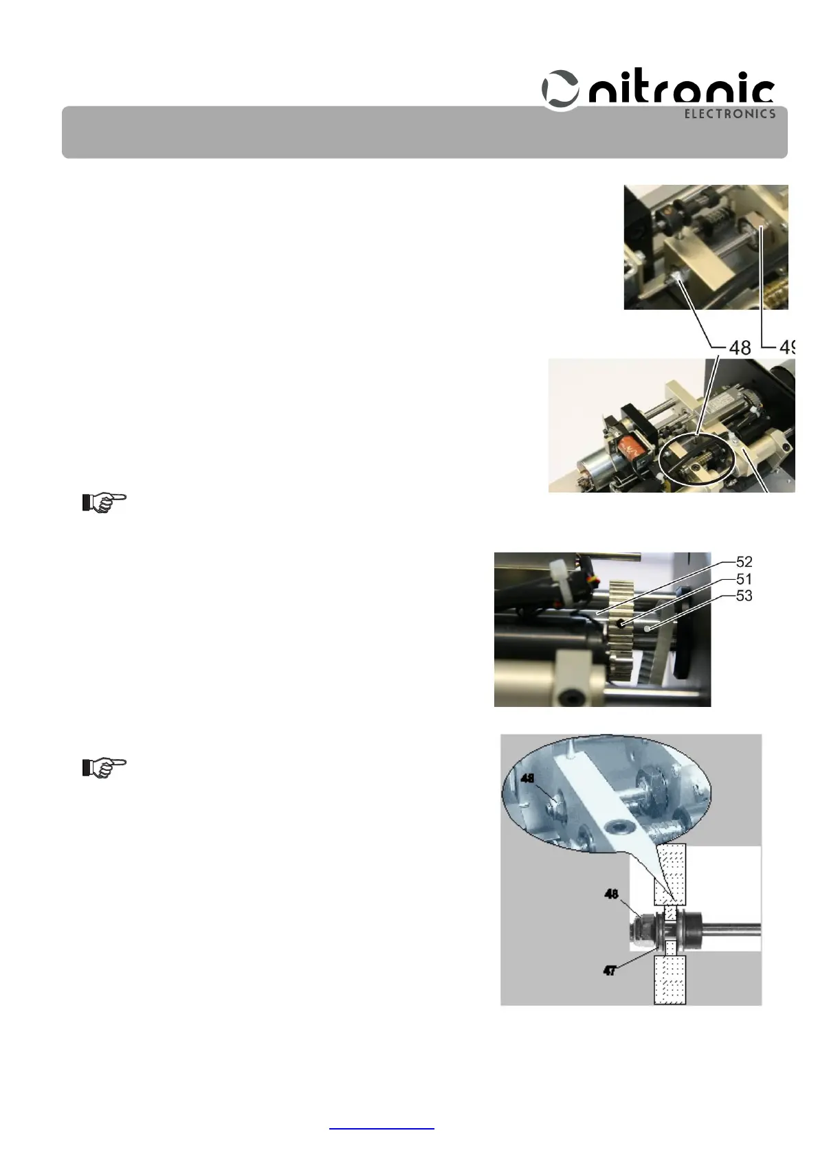
• Unscrew and remove locknut (48) (Fig. 37).
• Unscrew nut (49) of the stripping shaft (Fig. 37).
If an L is punched into the motor carrier (50) the nut (49) has a left-hand thread
(Fig. 37).
• Loosen the set screw (51) by approx. 4 turns and pull the
stripping shaft (52) out of the machine (Fig. 38).
• Install a new belt and mount the stripping shaft (52) in
reverse order (Fig. 38).
When tightening locknut (48)
make sure minimum clearance
exists between the nut and the
counter-washer (47) of the bear-
ing (Fig. 39).
Afterwards, the trigger device and grippers must be adjusted
again (page 37, and 40).
Fig. 38. Dismantle stripping shaft
Fig. 39. Axial bearing clearance