Battery connector
The battery connector is a spring connector. It has three springs;
•
BSI (Battery size indicator)
•
GND (Ground)
•
VBAT (Battery voltage)
The BSI line is used to recognize the battery capacity by a battery internal pull down resistor.
Charging
This phone is charged through a separate charger connector.
Charging is controlled by energy management, and external components are needed to protect the baseband
module against EMC, reverse polarity and transient frequency deviation.
Complementary USB charging is supported as well, in case the phone is connected to a PC or to a dedicated
USB charger.
Normal and extreme voltages
Energy management is mainly carried out in the ASIC PEARL_J. These circuits contain a number of regulators.
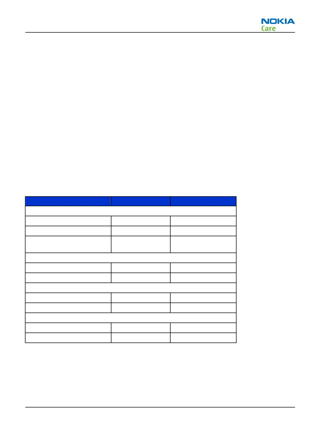
In the table below normal and extreme voltages are shown when a BL-5C battery is used.
Table 11 Nominal voltages
Voltage Voltage [V] Condition
General Conditions
Nominal voltage 4.0
Lower extreme voltage 3.145
Higher extreme voltage (fast
charging) 4.23
HW Shutdown Voltages
Vmstr+ 2.1 ± 0.1 Off to on
Vmstr- 1.9 ± 0.1 On to off
SW Shutdown Voltages
Sw shutdown 3.106 In call
Sw shutdown 3.2 In idle
Min Operating Voltage
Vcoff+ 2.9 ± 0.1 Off to on
Vcoff- 2.6 ± 0.1 On to off
Power key and system power-up
When the battery is placed in the phone the power key circuits are energized. When the power key is pressed,
the system boots up (if an adequate battery voltage is present).
Power down can be initiated by pressing the power key again (the system is powered down with the aid of
SW). The power key is connected to EM ASIC N2200 (PEARL_J) via PWRONX signal.
RM-721; RM-722
System Module
Issue 1 COMPANY CONFIDENTIAL Page 5 – 9
Copyright © 2011 Nokia. All rights reserved.