iii
Figures
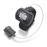
Figure 1. Front Display (Startup Screen).............................................................. 5
Figure 2. Comparison of Full and Partial Display................................................ 11
Figure 3. Remove Battery Door.......................................................................... 12
Figure 4. Insert Batteries.................................................................................... 12
Figure 5. Ring Strap ........................................................................................... 13
Figure 6. Thread Ring Strap............................................................................... 14
Figure 7. Attach Ring Strap................................................................................ 14
Figure 8. Adjustable Strap.................................................................................. 15
Figure 9. Thread Adjustable Wrist Strap ............................................................ 16
Figure 10. Attach Adjustable Wrist Strap ........................................................... 16
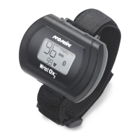
Figure 11. Device with Wrist Straps Attached (Front and Back Views).............. 17
Figure 12. Attach Sensor.................................................................................... 18
Figure 13. Verify Two-Piece Wrist Band Attachment ......................................... 19
Figure 14. Thread and Tighten Two-Piece Wrist Band ...................................... 20
Figure 15. Fasten Two-Piece Wrist Band........................................................... 20
Figure 16. Apply Sensor to Patient .................................................................... 21
Figure 17. Verify Single Strap Attachment ......................................................... 21
Figure 18. Thread Single Strap ......................................................................... 22
Figure 19. Tighten Single Strap.......................................................................... 22
Figure 20. Fasten Single Strap........................................................................... 23
Figure 21. Apply Sensor to Patient..................................................................... 23
Figure 22. nVISION Settings Window ................................................................. 31
Tables
Table 1. Labeling Symbols.................................................................................. 4
Table 2. Error Codes......................................................................................... 25
Table 3. Electromagnetic Emissions ................................................................. 37
Table 4. Electromagnetic Immunity................................................................... 38
Table 5. Guidance and Manufacturer’s Declaration—
Electromagnetic Immunity ................................................................ 39
Table 6. Recommended Separation Distances................................................. 40