NORDAC FLEX (SK 200E ... SK 235E) – Brief instructions for Frequency Inverters
88 BU 0240 en-US-4920
Pos: 69 6 /Anlei tung en/El ektr onik/FU und Star ter/6 . Meld ungen zum Betr iebsz usta nd/Mel dunge n Eins chalts perr e (Tabel le nüb erschr if t) @ 3\mod_1361803467385_14638.docx @ 59942 @ 5 @ 1
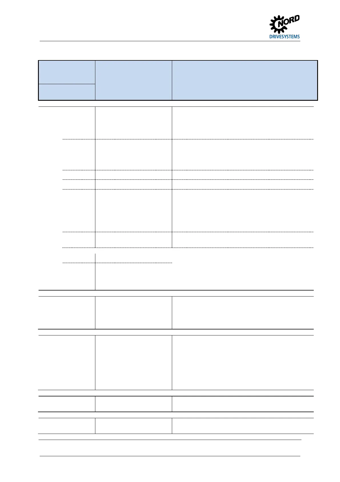
Notifications switch-on block, "not ready"
Display in the
SimpleBox /
ControlBox
Reason:
Text in the ParameterBox
Cause
• Remedy
Group Details in
P700 [-03]
Pos: 69 7 /Anlei tu nge n/El ektr onik /FU un d St art er/6 . M eld ung en z um B etr iebs zus ta nd/S törm el dung en (Auf list ung )/I nfor ma tio n I0 00_0 1 [S K 18 0E . .. SK 5xxE /SK 500P] @ 2\mod_1347457775195_14638.docx @ 47348 @ @ 1
I000
0.1 Disable voltage from IO
If the "disable voltage" function is parameterized, input
(P420/P480) is Low
• "Set high" input
• Check signal cable (broken cable)
0.2 IO fast stop If the function "fast stop" is parameterized, input
(P420/P480) is at low
• "Set high" input
• Check signal cable (broken cable)
0.3 Block voltage from bus • Bus operation (P509): control word bit 1 is "low"
0.4 Bus fast stop • Bus operation (P509): control word bit 2 is "low"
0.5 Enable on start Enable signal (control word, Dig I/O or Bus I/O) was already
applied during the initialization phase (after line power "ON",
or control voltage "ON"). Or electrical phase is lacking.
• Only issue enable signal after completion of
initialization (i.e. when the VFD is ready)
• Activation of "Automatic Start" (P428)
0.6 – 0.7 Reserved Information message for PLC see supplementary
instructions
Pos: 698 /A nleit ung en/El ek tr onik /FU und Star ter /6. M eldung en zum B etrie bsz ust and /Stör m eld ung en (A ufli st ung)/ Inf orm ati on I 000 _02-Erg änz ung 08 und 09 [ SK 1 80E ... SK 5xx E/SK 500 P] @ 10\mod_1455725649528_14638.docx @ 306333 @ @ 1
0.8 Right direction blocked Switch-on block with inverter shut-off activated by:
P540 or by "Enable right block" (P420 = 31, 73) or "Enable
left block" (P420 = 32, 74),
The variable frequency drive switches to "Ready for
switching on" status
0.9 Left direction blocked
Pos: 699 /A nleit ung en/El ek tr onik /FU und Star ter /6. M eldung en zum B etrie bsz ust and /Stör m eld ung en (A ufli st ung)/ Inf orm ati on I 006 [SK 1 80E ... SK 5xx E, außer SK 5 00P] @ 2\mod_1347457929759_14638.docx @ 47373 @ @ 1
I006
1)
6.0 Charging error Charging relay not energized, because:
• Line/DC link voltage too low
• Line voltage failure
• Evacuation run active ((P420)/(P480))
Pos: 700 /A nleit ung en/El ek tr onik /FU und Star ter /6. M eldung en zum B etrie bsz ust and /Stör m eld ung en (A ufli st ung)/ Inf orm ati on I 011 [SK 180E . .. SK 5xxE/S K 500P] @ 2\mod_1347457936856_14638.docx @ 47398 @ @ 1
I011 11.0 Analog Stop If an analog input of the variable frequency drive or a
connected IO extension is configured to detect cable breaks
(2-10 V signal or 4-20 mA signal), the variable frequency
drive switches to the status "ready for switch-on" if the
analog signal undershoots the value 1 V or 2 mA
This also occurs if the relevant analog input is
parameterized to function "0" ("no function").
• Check connection
Pos: 701 /A nleit ung en/El ek tr onik /FU und Star ter /6. M eldung en zum B etrie bsz ust and /Stör m eld ung en (A ufli st ung)/ Inf orm ati on I 014 "res erviert" [SK 200E ... SK 5xxE/ SK 5 00P] @ 2\mod_1347457944329_14638.docx @ 47423 @ @ 1
I014
1)
14.4 Reserved Information message for POSICON see supplementary
manual
Pos: 70 2 /Anlei tung en/El ektr onik/FU und Star ter/6 . Meld ungen zum Betr iebs zus ta nd/S törm el dung en (Auf list ung )/I nfor ma tio n I0 18 "r es ervi ert" [S K 2xx E/ SK 5 xxE / SK 2xx E-FD S/SK 50 0P] @ 2\mod_1347457946544_14638.docx @ 47448 @ @ 1
I018
1)
18.0 Reserved Information message for "Safe stop" function see
supplementary manual
Pos: 703 /A nleit ung en/El ek tr onik /FU und Star ter /6. M eldung en zum B etrie bsz ust and /Stör m eld ung en (A ufli st ung)/ Inf orm ati on - Ken nzeich nung "Ni cht ber eit" @ 20 \mod_1513067472948_14638.docx @ 2375119 @ @ 1
1) Indication of operating mode (message) on the Parameter Box or virtual operating unit of the NORD CON-Software: "Not ready"
Pos: 70 4 /Allg emein/ Allg emeing ültig e Module/---------Sei tenum br uch k omp akt --------- @ 13\mod_1476369695906_0.docx @ 2265496 @ @ 1
 Loading...


